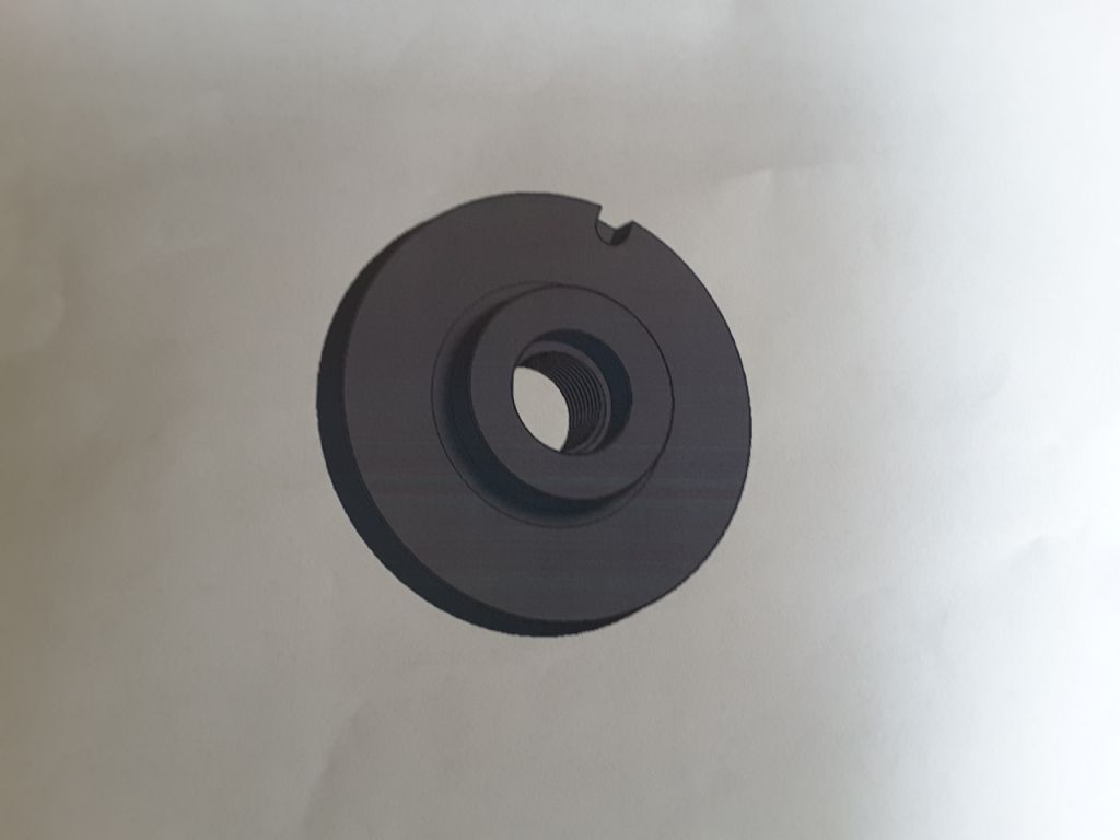
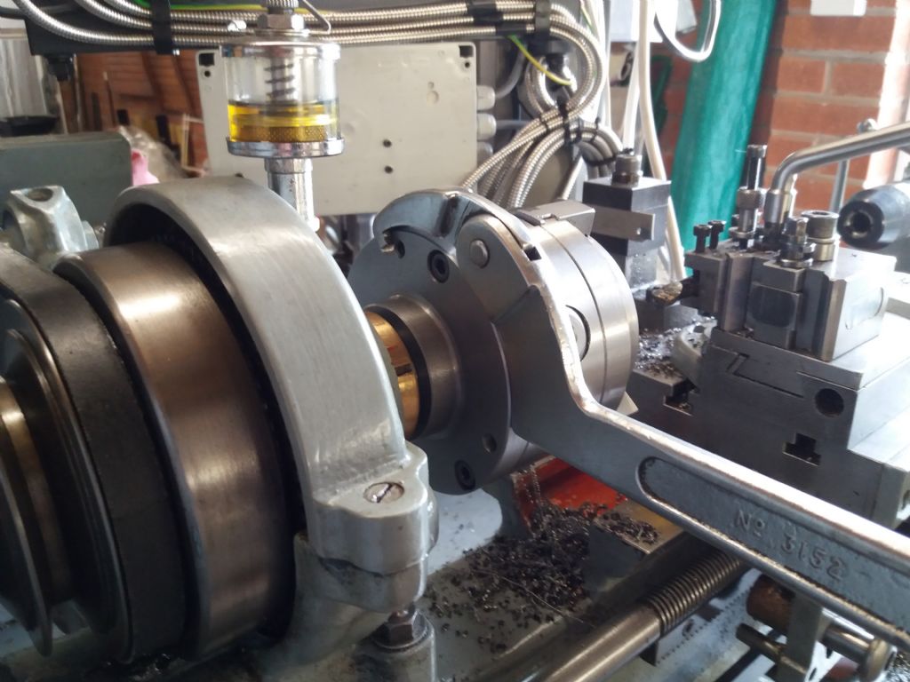
Myford/ Drummond M Type chuck back plate.
Myford/ Drummond M Type chuck back plate.
- This topic has 13 replies, 8 voices, and was last updated 8 June 2019 at 20:51 by
 Bazyle.
 Bazyle.
 David George 1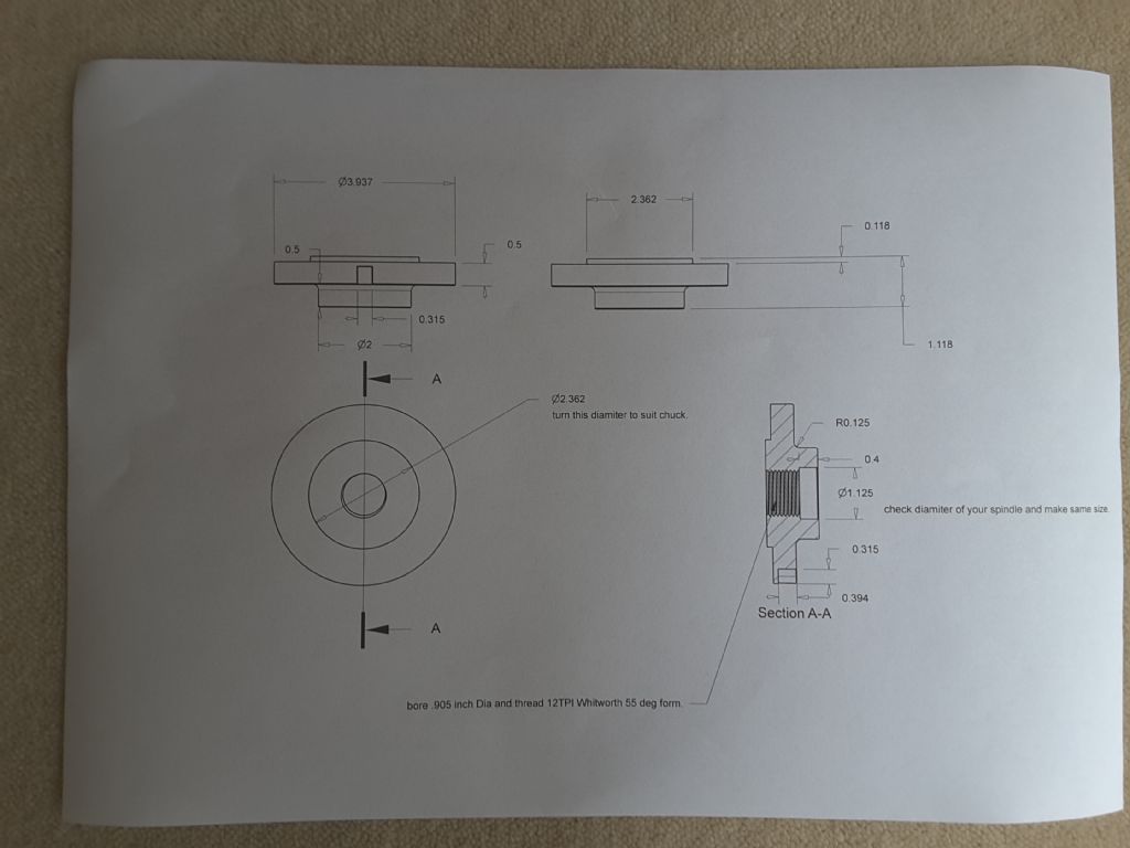
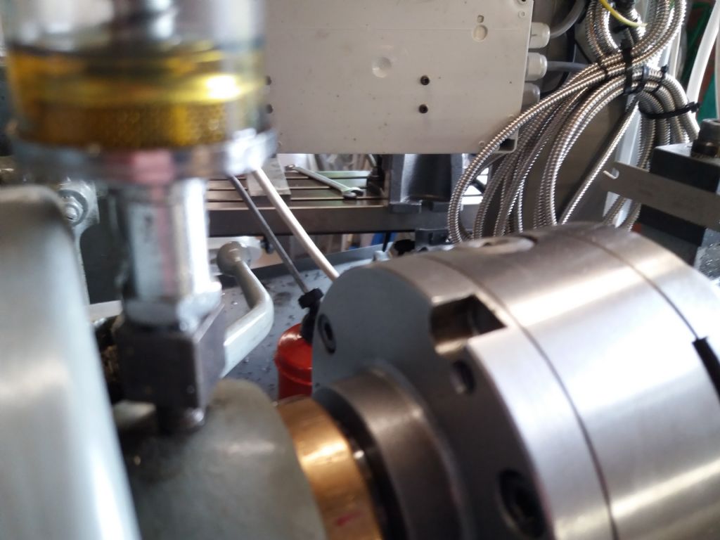
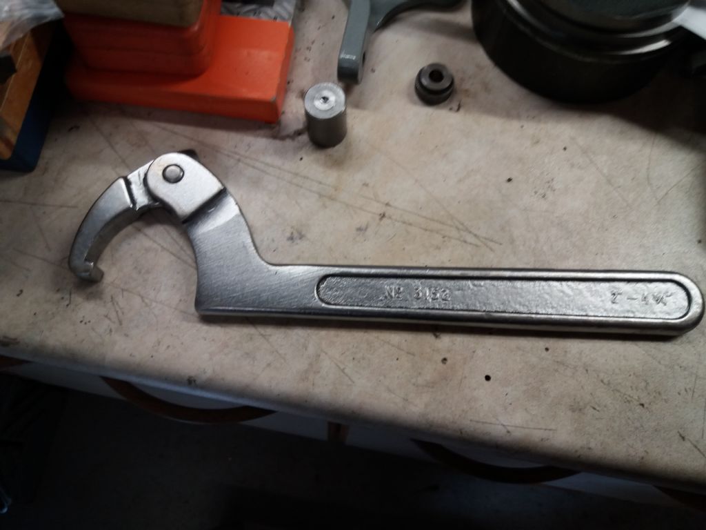
 JohnF
JohnF Lee Rogers
 colin hawes
 John MC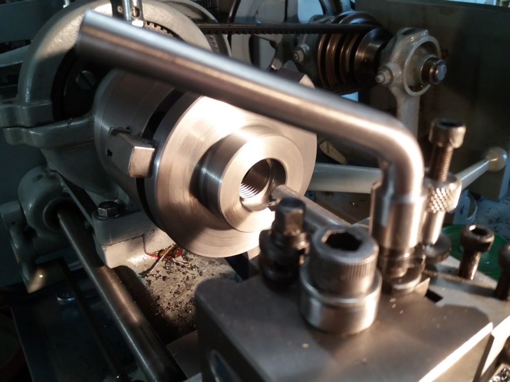
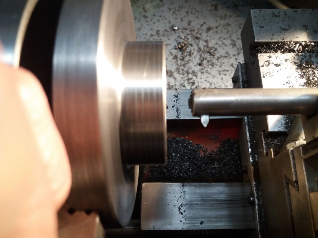
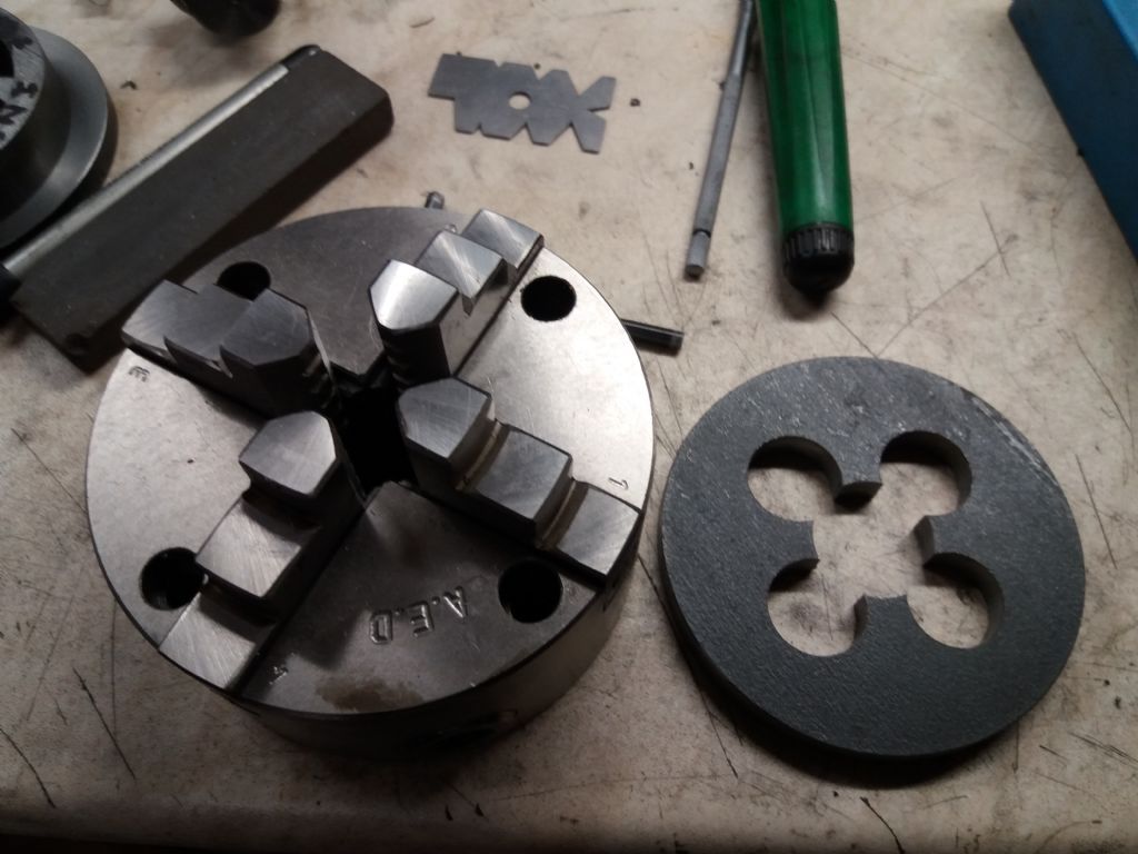
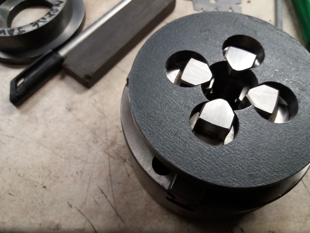
 geoff walker 1
 Roderick Jenkins
 Bazyle
- Please log in to reply to this topic. Registering is free and easy using the links on the menu at the top of this page.
Latest Replies
-
- Topic
- Voices
- Last Post
-
-
Stuart twin compound
Started by:
teamricky
in: Stationary engines
- 3
-
20 October 2026 at 22:09
Chris Gunn
-
Trying a new controller
Started by:
John Haine
in: CNC machines, Home builds, Conversions, ELS, automation, software, etc tools
- 4
-
20 October 2026 at 21:54
Huub
-
Rivetting with a hydraulic press
1
2
Started by:
Martin Johnson 1
in: Workshop Tools and Tooling
- 18
-
20 October 2026 at 21:37
Macolm
-
Layerling – new free CAD software for 3D printing
Started by:
Graham Stoppani
in: CAD – Technical drawing & design
- 7
-
20 October 2026 at 21:03
Fulmen
-
Model Turbines
1
2
…
26
27
Started by:
Turbine Guy
in: Stationary engines
- 28
-
20 October 2026 at 19:56
Turbine Guy
-
Close-coupled Tees (Underfloor heating)
Started by:
Andy Stopford
in: The Tea Room
- 5
-
20 October 2026 at 19:42
Andy Stopford
-
Model seed drill.
Started by:
colingp125halls
in: Introduce Yourself – New members start here!
- 3
-
20 October 2026 at 16:12
JasonB
-
ML7 change gear caluclator
Started by:
drnewcomb
in: Manual machine tools
- 6
-
20 October 2026 at 11:08
Howard Lewis
-
Pencil Sharpener
1
2
Started by:
Vic
in: The Tea Room
- 18
-
20 October 2026 at 09:49
Michael Gilligan
-
LAzar egde finder
Started by:
ian Holdsworth
in: Beginners questions
- 6
-
20 October 2026 at 09:32
Hollowpoint
-
ML10 and Chuck cleaning Information
1
2
Started by:
starjump
in: Beginners questions
- 10
-
20 October 2026 at 01:45
Grindstone Cowboy
-
carbide insert lathe tools
1
2
Started by:
davidwf
in: Workshop Tools and Tooling
- 16
-
19 October 2026 at 20:30
old mart
-
Coventry die head
Started by:
lug lord
in: Workshop Techniques
- 8
-
19 October 2026 at 18:27
John MC
-
The Latest INDEX to Model Engineer & Workshop (Also past issues of MEW)
1
2
3
Started by:
David Frith
in: Model Engineer & Workshop
- 7
-
19 October 2026 at 17:04
David Frith
-
Rush of blood or not
Started by:
BOB BLACKSHAW 1
in: 3D Printers and 3D Printing
- 8
-
19 October 2026 at 16:56
BOB BLACKSHAW 1
-
Making a Lathe Bench for a Myford ML10
1
2
Started by:
starjump
in: Beginners questions
- 11
-
19 October 2026 at 13:17
southernchap
-
PROGRESS
Started by:
Phillip weaver
in: Introduce Yourself – New members start here!
- 5
-
19 October 2026 at 12:01
Phillip weaver
-
Su251-53
1
2
Started by:
parovoz
in: Locomotives
- 15
-
19 October 2026 at 11:04
noel shelley
-
What Did You Do Today 2026
1
2
…
8
9
Started by:
JasonB
in: The Tea Room
- 54
-
18 October 2026 at 20:28
Bazyle
-
The Sunday bazar
1
2
Started by:
Sonic Escape
in: The Tea Room
- 19
-
18 October 2026 at 12:44
Sonic Escape
-
Myford ML4 Identification
Started by:
Steven Volz
in: Manual machine tools
- 7
-
18 October 2026 at 04:43
Steven Volz
-
Richard B’s Minnie.
Started by:
Richard B
in: Traction engines
- 4
-
17 October 2026 at 22:22
Richard B
-
Weight of Myford Super 7 / ML7R
Started by:
Andrew Tinsley
in: General Questions
- 6
-
17 October 2026 at 21:06
Zan
-
Scroll Saw Blades for Steel
1
2
Started by:
James A
in: Workshop Tools and Tooling
- 15
-
17 October 2026 at 21:05
bernard towers
-
Bridge collapse
1
2
Started by:
JA
in: The Tea Room
- 13
-
17 October 2026 at 18:21
JA
-
Stuart twin compound
 teamricky
  Chris Gunn
 John Haine
  Huub
Huub Martin Johnson 1
  Macolm
 Graham Stoppani
  Fulmen
 Turbine Guy
  Andy Stopford
  colingp125halls
  JasonB
 drnewcomb
  Howard Lewis
 Vic
Vic  Michael Gilligan
 ian Holdsworth
  Hollowpoint
 starjump
  Grindstone Cowboy
 davidwf
  old mart
 lug lord
  John MC
 David Frith
  BOB BLACKSHAW 1
  southernchap
 Phillip weaver
  parovoz
  noel shelley
 Sonic Escape
  Steven Volz
  Richard B
  Andrew Tinsley
  Zan
Zan James A
  bernard towers
 JA
JA