Huron NU3 Milling m/c adaptor

Huron NU3 Milling m/c adaptor

Home Forums Beginners questions Huron NU3 Milling m/c adaptor

Viewing 16 posts - 1 through 16 (of 16 total)
  • Author
    Posts
  • #273296
    Steve Butler 1
    Participant
      @stevebutler1

      Hi I have been asked if i could make an adaptor for a NU4 Huron milling m/c vertical drilling or milling head attachment with a 40 INT drive

      Has anybody got one or any information about one please

      Or what would be the best material to make one out of Ie. EN8

      I have taken dimensions to make one but if i could lay my hands on one it would be better and easyier

      Thanks steve butler

      #8453
      Steve Butler 1
      Participant
        @stevebutler1

        Make or buy

        #273305
        John Haine
        Participant
          @johnhaine32865

          Steve, I assume this is a 40 Int taper to "something" adapter? I'm fairly certain you can buy unmachined blanks but might need a 40INT taper socket to hold it in. I've made a 30 INT taper to fit my CNC mill straight from the dimensions, by CNC turning, and it worked fine. The 40 INT dimension specs are findable on the web I think. But most INT tapers have easily available adapters I think for things like ER collets?

          #273327
          Bikepete
          Participant
            @bikepete

            I've always rather lusted after a Huron milling machine… oh for a bigger shed…

            But anyway, could you maybe be clearer what the adaptor is for? To adapt the head to another mill maybe?

            I'm guessing the head is one of the two recently ended on Ebay?

            #273345
            Muzzer
            Participant
              @muzzer

              Re: ISO40 (= INT40, IIRC), the dimensions are given in DIN2080 which you can find by Googling it eg this.

              I'm guessing you are hoping to make a socket to receive the taper?

              Murray

              Edited By Muzzer on 22/12/2016 21:43:31

              #273394
              Ex contributor
              Participant
                @mgnbuk

                I suspect that this adapter will be an ISO40 taper with some form of drive dog on the front, the form of which will mate with a mirror image version mounted on the head input shaft. i.e. a disc with a slot across the face with taper on the back, which mates with a tenon on the input shaft. Or a female spline in the taper shank that mates with a short splined input shaft on the head.

                I should not be too difficult to measure up the input arrangement to the head to reverse engineer a suitable adapter to fit. As has been stated above, the ISO 40 dimensions are readily available, as are "tool blanks" like this example **LINK**

                HTH

                Nigel B

                #273408
                Steve Butler 1
                Participant
                  @stevebutler1

                  Hi all and thanks for the feedback

                  To Bikepete there is one on ebay item no eBay item number:

                  221963367303
                  The one i have to make one for is similar to this one showing the adaptor next to the head i don't now of the heads origin
                  I was thinking of getting a drill chuck arbor without the chuck and turning it down parallel l was then going to turn up a drive dog and mill the teeth or mill the gaps and fit key steel and then fit to chuck adaptor
                  SB
                  #273433
                  Raymond Anderson
                  Participant
                    @raymondanderson34407

                    As far as I know the ISO number identifies the taper ie 30/40/50/60 and Din 2080 identifies the method of holding in the machine spindle. For instance a BT 40 is the same taper as ISO /SK 40 and they are both the same taper as ISO 40 / DIN 2080. the difference is only in how they are held.

                    The ISO 30 40 et al is suited to auto toolchangers [ hence the grove in the flange ] Whilst those made to ISO / Din 2080 have solid flanges ie no groove. . They are all 7.24 tapers whether BTMas /SK or 2080.

                    #273451
                    Ketan Swali
                    Participant
                      @ketanswali79440

                      Steve,

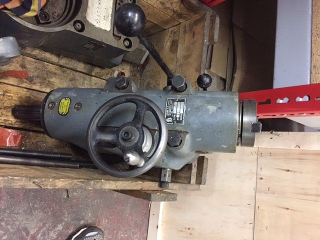
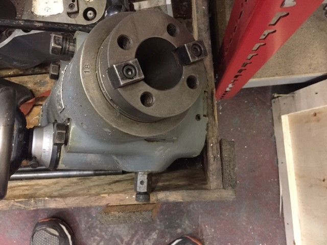
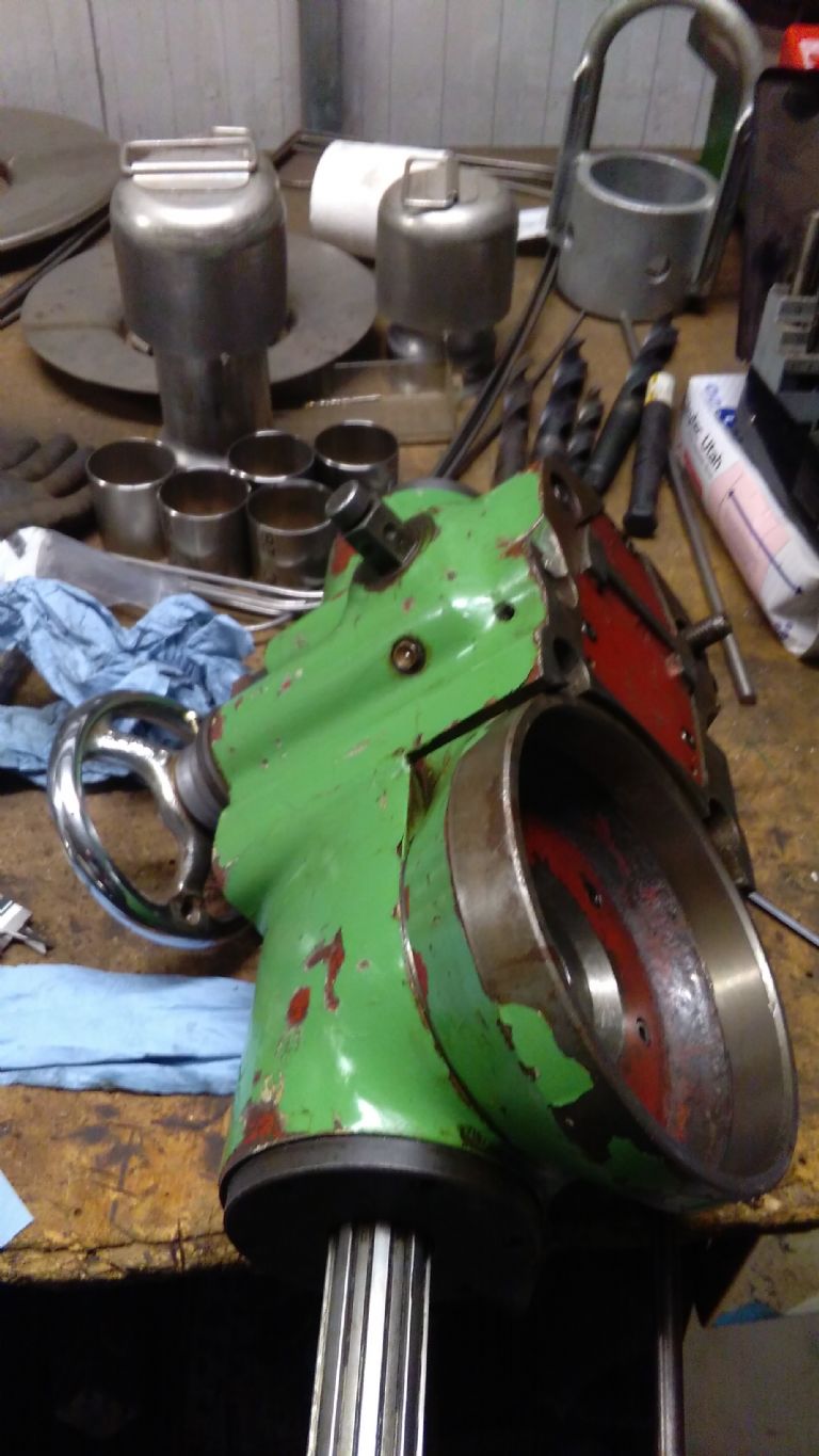
                      Are you able to say what is the purpose/intended use of such an adaptor?… I have not come across such an adaptor. We have a Huron MU6 in our workshop. It came with a pallet full of accessories. I went through it this afternoon and found the drilling attachment… pictures below, but unable to find an adaptor of the type shown in the ebay picture or your description. So am a bit curious about the use of such an adaptor.

                      huron drilling attachment1.jpg

                      huron drill attachment.jpg

                      Ketan at ARC

                      #273455
                      Muzzer
                      Participant
                        @muzzer

                        They are all the same taper angle and the 30/40/50 etc denotes the size, 30 being the smallest. The difference between INT40 / ISO40 (ie DIN2080) and BT, SK etc is that the DIN2080 has a short parallel sided extension at the small end, rather like the American NMTB. Consequently the drawbar required for the DIN2080 and NMTB is shorter than for the others.

                        The NMTB40 / NT40 is an imperial version, often with 1/2" UNC thread.

                        ISO40 / INT40 / BT40 etc generally seem to be M16 thread. With a longer drawbar you should be able to use BT40 tooling instead of INT40 (BT40 is easier to find).

                        Given that you can buy decent quality toolholders for £20 a pop and generally you want as many as you can get your hands on, why not save your efforts for something else? Why would you want just one holder?

                        Murray

                        PS: when Steve talks about an "adaptor", I suspect he is simply talking about an ISO40 toolholder. As I said, they are freely available and ideally he'd be trying to find a bucket load of them.

                        Edited By Muzzer on 23/12/2016 17:53:54

                        #273456
                        Ketan Swali
                        Participant
                          @ketanswali79440

                          Murray,

                          It looks like Steve 'wants to/needs to make' an INT40 adaptor like the one in the ebay picture – which has some kind of splines at the working end of the adaptor….for some kind of specific application… see ebay listing: 221963367303 and zoom in on the adaptor in the picture.

                          Ketan at ARC.

                          #273464
                          Ex contributor
                          Participant
                            @mgnbuk

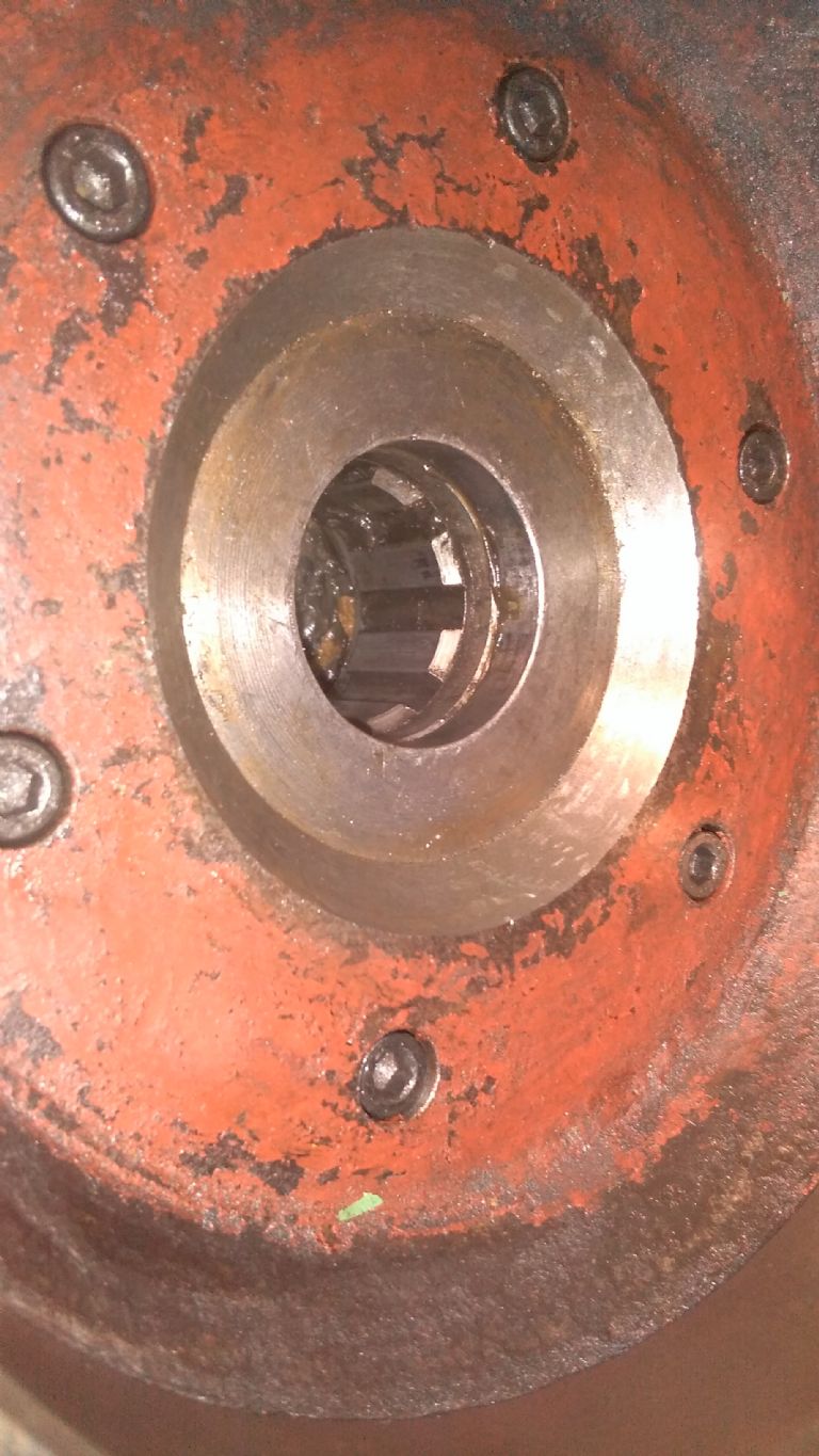
                            "Adapter" here means "drive shaft". The Huron NU4 appears to be a horizontal mill – the "adapter" changes the horizontal 40 taper into a short splined drive shaft that engages with the input gear to the right angle attachment. If Ketan could take another picture of the mounting face of his right angle head (to the right of the spindle nose on the bottom picture posted above), then the female spline on the input shaft should be visible.

                            The Lagun double angle heads we used to fit to Butler Elgamills at the last place I worked were a little less sophisticated – the input shaft to the head was a disc with a slot across that was then same width & depth as the horizontal spindle drive dogs. No "adapter" required here, just care making the plate to hold the head onto the end of the ram the correct thickness so the drive disc in the head just cleared the horizontal spindle front face.

                            Nigel B.

                            #273524
                            Steve Butler 1
                            Participant
                              @stevebutler1

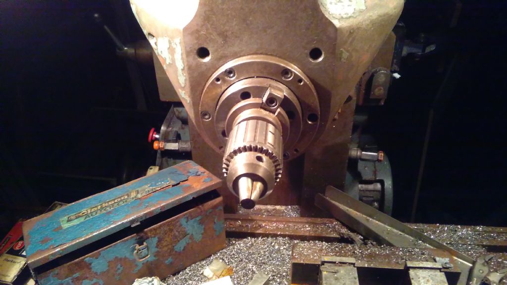
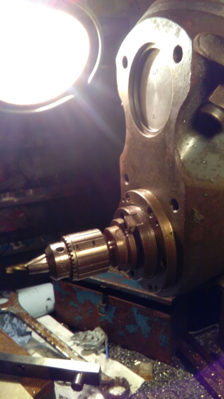
                              img_20161220_165737.jpgimg_20161220_165728.jpgimg_20161220_165647.jpgimg_20161220_165443.jpgHi all sb again Apologys for not being clearer. As Nigel has gessed it is the drive dog adaptor i need to make

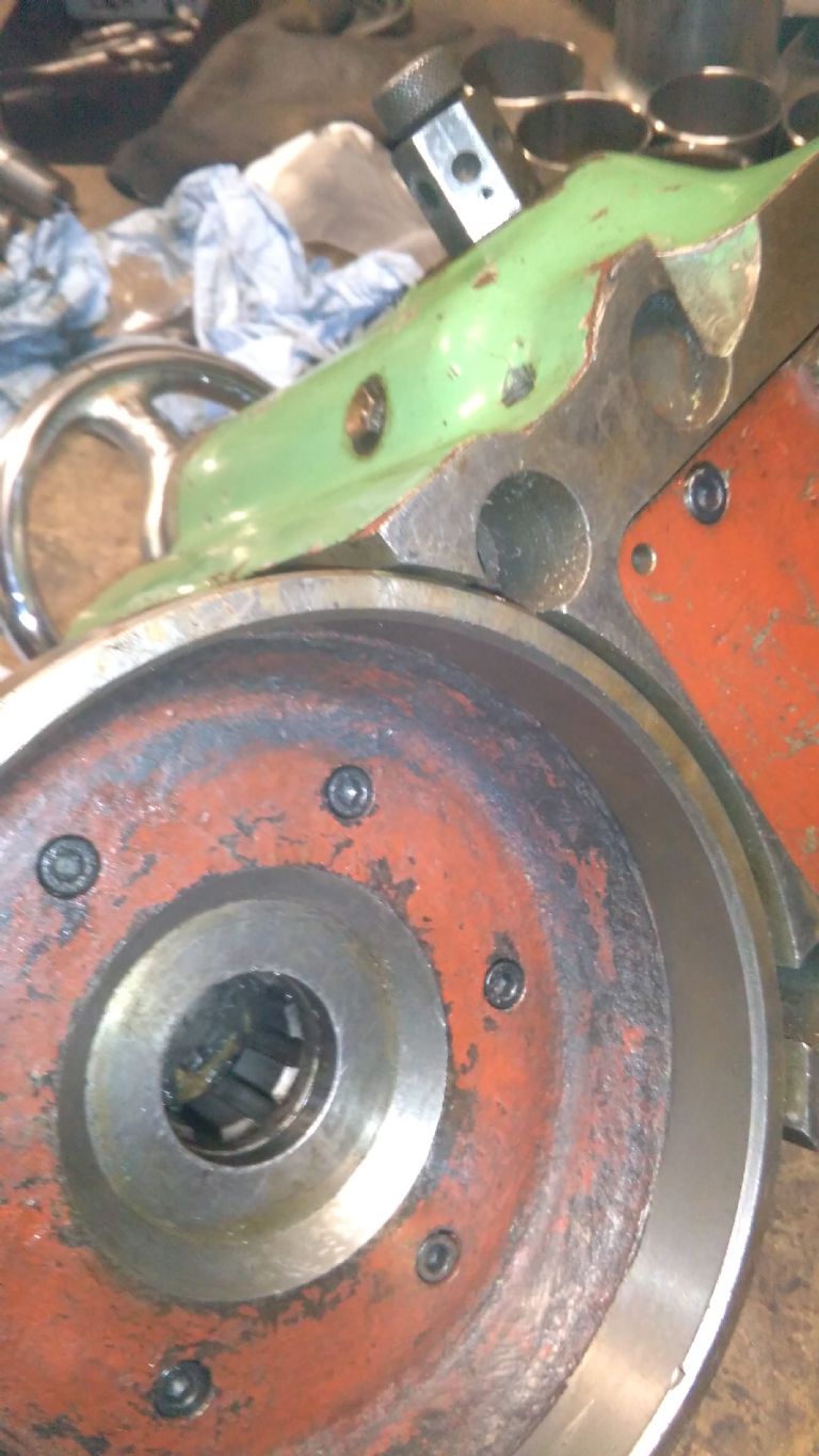
                              Hopefully i have sent some photo's of the drilling / milling head that the adaptor fits between (INT 40 male one end and 8 tooth drive dog other end) hope this makes it clearer as previously thought i would possibly make one useing a drill chuck INT 40 drive turned down parellel and make a drive gear out of some EN8' ish material or what would be better

                              Sorry again for not being clearer and thanks again for all your feedback Steve img_20161220_165407.jpgB

                              #273575
                              Ketan Swali
                              Participant
                                @ketanswali79440

                                Thanks for the clarification Nigel and Steve. I get the application now, although I know that your original question still needs a resolution.

                                Ketan at ARC.

                                #273577
                                Nick Hughes
                                Participant
                                  @nickhughes97026

                                  You can buy Tool Blanks as a starting point:- **LINK**

                                  Nick.

                                  #273579
                                  Ex contributor
                                  Participant
                                    @mgnbuk

                                    Apologies for the scabby sketch below (hopefully – this forum software is a pain !), but I hope this will show why I don't think a standard tool will be easy to modify. Top section shows how a standard flanged tool fits & bottom section shows how I think the splined shaft adapter fits the spindle

                                    The splined drive shaft (adapter) shown in the Ebay link has two driving tabs, not a drive flange with two drive dog cutouts like a standard tool. The picture of the input spline at the back of the right angle head shows very little clearance between the back of the head casting for the spindle nose. I think that the splined drive shaft is fitted to the spindle with the drive dogs removed, so that the drive tabs are below the spindle front face. On a standard tool the existing drive flange & some of the taper will have to be removed to allow an additional part (preferably part of the splined piece) to have the tabs machined on such that the tabs fit below the spindle nose front face. Standard tools (including blank arbours) have the taper shank & drive flange hardened, so removing them will not be easy. Probably better to try to make the "adapter" as one piece as shown in the listing. To find the taper diameter at the drive base of the drive dog slot, remove the dogs, put some layout blue (or indelible marker pen) on a cleaned tool shank, insert the tool in the spindle & scribe the tool shank from teh bottom of the slots, then measure the diameter on the taper across the scribed lines. For what it is doing, I don't think you need a "full" taper, so the middle portion could be relieved to give a two tapered bands (one at each end) to locate in the spindle taper.

                                    HTH

                                    Nigel B

                                    file0105.jpg

                                  Viewing 16 posts - 1 through 16 (of 16 total)
                                  • Please log in to reply to this topic. Registering is free and easy using the links on the menu at the top of this page.

                                  Latest Replies

                                  Home Forums Beginners questions Topics

                                  Viewing 25 topics - 1 through 25 (of 25 total)
                                  Viewing 25 topics - 1 through 25 (of 25 total)

                                  View full reply list.