David Fenner’s headstock dividing tool

David Fenner’s headstock dividing tool

Home Forums Beginners questions David Fenner’s headstock dividing tool

Viewing 17 posts - 1 through 17 (of 17 total)
  • Author
    Posts
  • #117038
    JamesF
    Participant
      @jamesf

      I'm reading through David Fenner's "The Mini-Lathe" at the moment and looking at making the headstock dividing attachment. I know this perhaps isn't the best way to achieve the ends, but partly I want to follow his instructions because I'm pretty much a complete beginner and having to teach myself so it's good practice at carrying out different turning operations.

      What isn't clear to me is how the arbor engages with the headstock spindle. That doesn't appear to be explicitly explained in the book. I'm coming to the conclusion that the tapered plug is drawn into the tapered section of the arbor when the changewheel is bolted onto the other end, expanding the end of the arbor slightly and clamping it into the inside of the spindle. This leads me to the further conclusions that the arbor must be in place before the nut at the external end is nipped up and that the length of the outer section of the arbor must be fractionally shorter than the thickness of the hub of the changewheel.

      Is my interpretation correct?

      Thanks,

      James

      #6662
      JamesF
      Participant
        @jamesf
        #117168
        Robbo
        Participant
          @robbo

          James.

          This follows the usual procedure for fitting an expanding arbour inside the spindle. The arbour has a 12mm section on the outer end on which to mount the changewheel. The arbour is drilled right through to allow a threaded drawbar to pass through, and the inside end is drilled 17mm, has a taper on the inside at the end, and has 4 slits sawn logitudinally at this end. this allows the end of the arbour to open up inside the spindle. A nut with a matching taper is produced and threaded to take the drawbar.

          When the drawbar is tightened it pulls the tapered nut into the arbour and expands it to grip the inside of the spindle, so that when the arbour is turned the spindle rotates the same amount. The changewheel is fixed to the outer end, rotated the required number of teeth, and locked in position by the detent.

          The drawbar also secures the changewheel.  I don't know the thickness of the changewheel, but the small stub is probably slightly less.  A washer under the nut wouild be a good idea.

          So the sequence would be to place the arbour into the spindle, draw up the tapered nut using the drawbar, then remove the drawbar nut and fit the changewheel, replace the drawbar nut and finally tighten, as there is only the drawbar nut to hold the changewheel in position. So probably best to turn the assembly when actually dividing by holding the chuck, to remove any possibility of the changewheel slipping.

          This lengthy dissertation really boils down to "Yes, you've worked it out correctly".

          I have not seen Dave's book, but it is made up of a series of article he wrote for MEW, and I did see those. I agree that as it was for beginners it could have been clearer, but fixing things in the spindle like this is such an everyday occurrence it probably wasn't noticed.

          In the articles, the thread was frequently broken to explain processes as they came up, so the construction of this simple accessory was spread about. I hope the book was better laid out.

          Phil

          Edited By Robbo on 17/04/2013 19:45:56

          Edited By Robbo on 17/04/2013 19:46:52

          #117182
          JamesF
          Participant
            @jamesf

            Thanks for the confirmation, Phil.

            The book isn't too bad, though I'd suggest it could still benefit from a little editing. I can't be too critical though. There's beginners and beginners. During the day I work in IT and whilst I can cope with simple electronics, am happy to get out the power tools for woodworking, can handle domestic electrics or plumbing and don't mind throwing a bit of concrete or mortar about, metalwork is pretty much virgin territory for me. Before I started reading Sparey barely four months ago I hadn't the first idea how to use a lathe nor even what the main parts were called. It wouldn't surprise me at all if the target audience for those articles wasn't a little better informed than me.

            Actually, come to think of it, I have done one piece of metalwork before. Must have been about 1978 in my first year at secondary school, when we made a boot scraper by brazing together some bent steel rod and a piece of plate…

            James

            #117192
            Sub Mandrel
            Participant
              @submandrel

              Hi James,

              Can I modestly suggest you make my mandrel handle.

              The add the indexing attachment. The notched end and adjustability so you can use any change gear mean you get a comprehensive range of divisions.

              I am still regularly using them. Ignore the editors comments about the concentricity of the mandrel bore, I checked mine and its less that 1 thou out.

              The one improvement I made was to attach a short lever onto the handle locking nut, so attaching and removing doesn't need a spanner and takes only a second or two.

              The big advantage with my design is that it only occupies the first inch of the mandrel, most other designs are several inches long to no good benefit.

              Neil

              #117204
              Robbo
              Participant
                @robbo

                Hi Neil,

                I take it these appeared in ME, as I only subscribe to MEW I only have access to MEW digital editions.

                Phil

                #117242
                Bazyle
                Participant
                  @bazyle

                  For future reference for those without digital access Neil's link is to ME, vol 193, isse 4230, 17 sept 2004 page 321. "setting up the Clarke CL300M lathe Mandrel handle"

                  I haven't read the article yet but something to take into account with all expanding plugs is when you undo it a minor annoyance can be if the taper plug sticks in the expanding bit and the draw in thread just moves back out of the assembly. Ok all it takes is a thump to free it but five seconds of thought during the desgn can arrange for the threaded part to have a shoulder to hold it in location wrt the expanding bit.

                  #117251
                  Chris Parsons
                  Participant
                    @chrisparsons64193

                    I have been having a go at this too – I have posted some photos, warts and all – look in my album?

                    Think the workings of this have been explained above, but tightening up the nut on the changewheel pulls the tapered 'plug' at the opposite end which makes the mandrel open up and grip the inside of the lathe spindle. You can see the photo of this while looking at the terrible job of cutting the slots to allow this to work! (the lesson learned was cut ALONG the mandrel not ACROSS it and the line might have been straight – this will annoy me so much I expect I will make another mandrel!)

                    My lathe is a Sieg SC4 and I mounted the support plate by removing (one at a time!) the cap screws holding something in the gearbox and making stand off hex spacers (in brass, it was the only bit of hex bar I had at the time)

                    My lathe has a 45 tooth gear which gave me the three divisions (15 teeth per division) I was after, and I 'notched' the plunger to let me use the top of the teeth too, giving me 6 (7.5 teeth per division)

                    I have other changewheels (quite a few) so will have no problem making up most divisions I want I think!

                    The plunger is not a great fit in the block which means there is a little bit of play so I might make another one of these too. (I am also learning and a complete beginner)

                    The slot in the swivel plate was to allow bigger gears to be used and keep the plunger aligned with the axis of the gear which did not seem to be considered in the original design?

                    You are welcome to ask me any questions you like, I also did this as a learning exercise and it seems to work reasonably well.

                    Best wishes

                    Chris

                    #117261
                    JamesF
                    Participant
                      @jamesf

                      Not sure I understand what you're getting at with the shoulder on the threaded part Bazyle. Can you expand a little? By "threaded part" do you mean the plug that expands the arbor, the idea being that the plug couldn't be drawn "too far" into the arbor?

                      A couple of modifications have occured to me over the last few days.

                      The first is that it might be nice to have a keyway to locate the changewheel rather than relying on squeezing the plastic wheel between the arbor and a washer to prevent it spinning.

                      The second is that the slots cut into the arbor to allow it to expand could have a slightly larger hole drilled through the wall at their ends to reduce mechanical stress at the ends of the cuts.

                      James

                      #117262
                      Gray62
                      Participant
                        @gray62

                        There is a design for a self releasing mandrel handle in MEW 117

                        Graeme

                        #117280
                        Sub Mandrel
                        Participant
                          @submandrel

                          These pictures may assist,

                          Neil

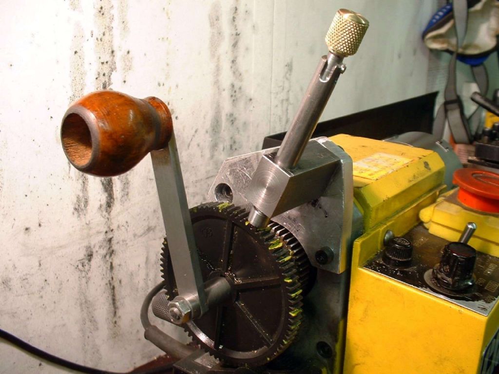
                          The dividing attachement and handle in place:

                          fitted to lathe close.jpg

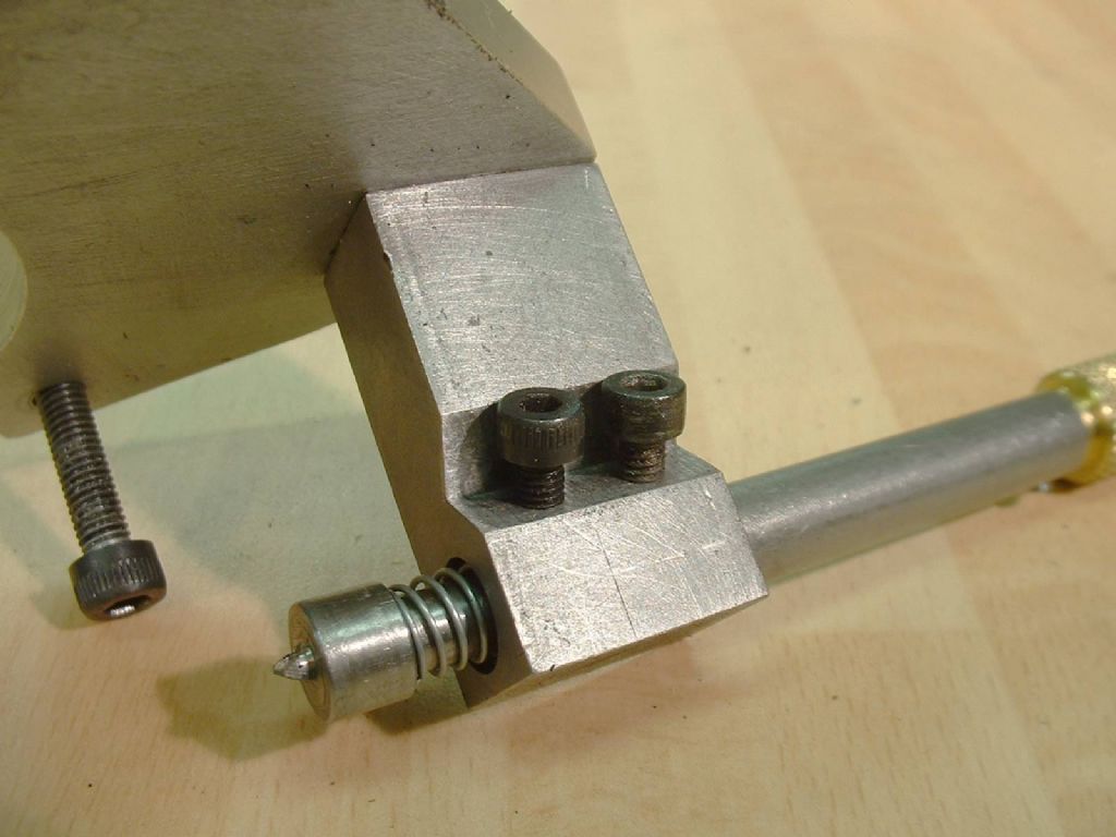
                          The sprung detent:

                          detail of detent holder.jpg

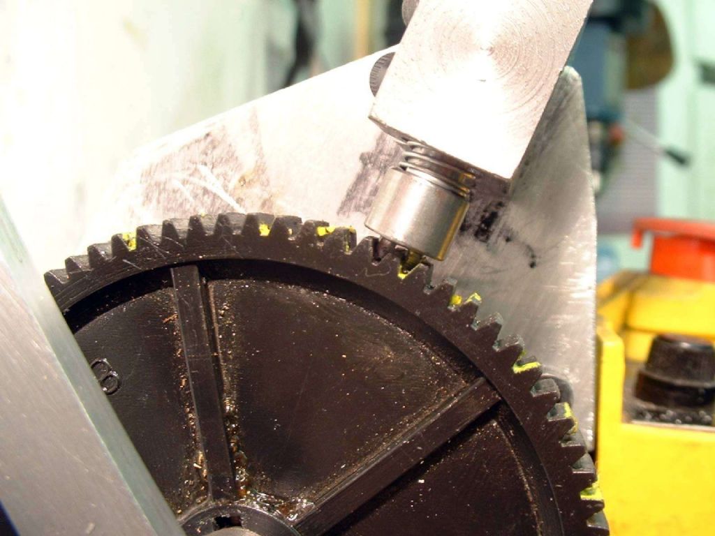
                          How the detent can bridge a tooth:

                          detent bridges two teeth.jpg

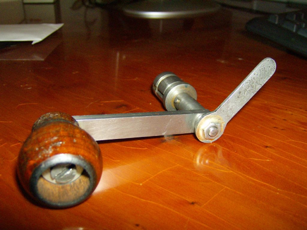
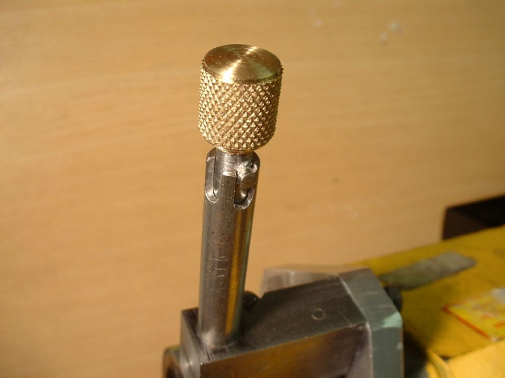
                          Just twist the lever and it releases rapidly with one hand,.the spring around the two 'floating' parts of the collet ensure it releases.

                          The two notches are for between and over a tooth:

                          top end of plunger.jpg

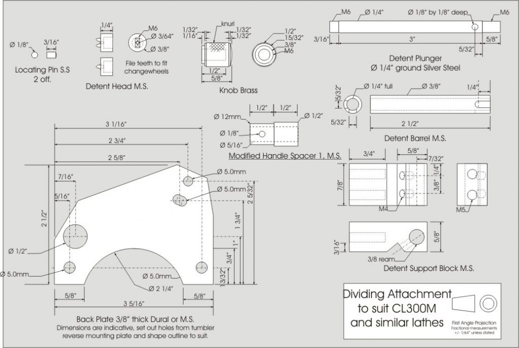
                          Drawing for the dividing attachment:

                          dividing attachment.jpg

                          Edited By Stub Mandrel on 18/04/2013 21:03:59

                          #117288
                          JamesF
                          Participant
                            @jamesf

                            That looks like a very neat design, Neil. Someone must have been a bit miffed when they found out you'd nicked their pipe bowl to use as a handle though.

                            James

                            #117307
                            Chris Parsons
                            Participant
                              @chrisparsons64193

                              Thank you Neil – that looks pretty good, think I might have a go at making this too, be good practise for converting from metric (I want to be able to use both Imperial and metric, my lathe is metric but I know Imperial drawings are very common)

                              It is always interesting to see different design approaches as well

                              Appreciate you posting the plan

                              Regards

                              Chris

                              #117358
                              Sub Mandrel
                              Participant
                                @submandrel

                                The handle is off a cheap pound shop hand drill!

                                Chris – you need to check the dimensions from eth lathe -all the others aren't particularly critical, use what you have handy.

                                Neil

                                #117360
                                Bazyle
                                Participant
                                  @bazyle

                                  More detail on my coment about releasing the taper.

                                  A common design involves a 'mandrel' that is drilled, an internal taper turned, and slit. Then a matching taper plug turned, drilled and threaded. A drawbar (bolt) draws the plug into the taper end of the mandrel to expand it. When unscrewed to release the plug, if it doesn't release, the drawbar backs out of the hole in the mandrel until it it given a tap to release the plug.
                                  However if the drawbar is made wider half way down on the plug screwed end, and the hole in the mandrel is narrower at the non tapered end then the drawbar can only be inserted from the tapered end. It has to stay in a fixed position locating on the shoulder formed at the change in width. So when unscrewed the plug is forced out giving positive release.

                                  Other configurations are possible which may be even better.

                                  Edited By Bazyle on 19/04/2013 20:28:27

                                  #117362
                                  Sub Mandrel
                                  Participant
                                    @submandrel

                                    Hi Bazyle,

                                    As made, on mie I had to loosen the nut and tap it, as you describe.

                                    I found the little stamped 'ring spanner' and silver soldered it to the nut, now you can turn the nut-lever wjhile holding the main handle in place single handed. the ergonomics of doing this keep the nut-lever pushed in, so it releases. Only 1/3rd of a turn is needed.

                                    I wish I could say I planned it to work that way, but it just came out like that.

                                    Neil

                                    #117368
                                    Bazyle
                                    Participant
                                      @bazyle

                                      It also depends on the lathe. On my Hobbymat any of the change gears can be fitted to the standard spindle end anyway. For a handle the spindle length is long enough for a thick ring which is half a dog clutch to fit semi-permanently behind the change wheel, . My handle is on a rod to locate it by gong down the bore but engages with the dog clutch so no screws to do up at all. Fitting or removing takes barely 2 seconds. I think I copied it from a design for the Myford in ME about 25 yrs ago.

                                    Viewing 17 posts - 1 through 17 (of 17 total)
                                    • Please log in to reply to this topic. Registering is free and easy using the links on the menu at the top of this page.

                                    Latest Replies

                                    Home Forums Beginners questions Topics

                                    Viewing 25 topics - 1 through 25 (of 25 total)
                                    Viewing 25 topics - 1 through 25 (of 25 total)

                                    View full reply list.