A QCTP question, or two

A QCTP question, or two

Home Forums Workshop Tools and Tooling A QCTP question, or two

Viewing 14 posts - 51 through 64 (of 64 total)
  • Author
    Posts
  • #218145
    John Hinkley
    Participant
      @johnhinkley26699

      Now that the drinking season is slowing down (a bit), I've had a chance to reflect on this question. Although it was a while ago, I now fecall that I used my 45 degree vee blocks to hold the toolholders on the mill table. If I remember correctly, it took a bit of fiddling about with clamps, angle plate, etc., but did it in the end. There's more than one way to skin a cat!

      John

      #218147
      Vic
      Participant
        @vic
        Posted by Michael Gilligan on 25/12/2015 17:19:15:

        For DIY enthusiasts, this thread might be of interest.

        MichaelG.

        I've seen this on another forum. It's interesting that he had two goes at cutting the V's. The first roughing cut made with the holders clamped in the vice at 45° and then a finishing cut with them clamped flat but with the head of the mill canted at presumably 45°. I'm guessing it's easier and more accurate to machine the holders with them flat in the vice? I think it's the way I'd do it if I didn't have a drill mill.

        #218183
        CotswoldsPhil
        Participant
          @cotswoldsphil

          I'm back with some more information which might be of interest.

          Just managed to upload the 3 photos after 3 attempts…so here goes.

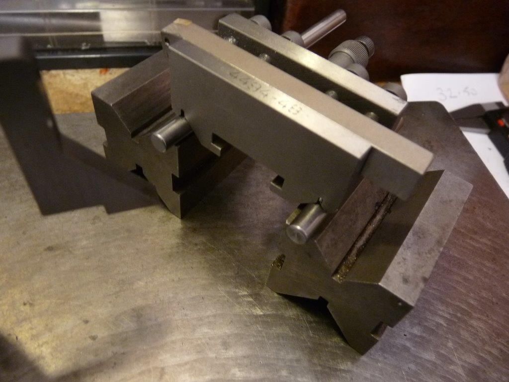
          Clive Foster suggested that I use round bars to support the holders whilst measuring, I can report that all the measurements made on round bars were within a couple of thou of the first set, where I used ground square bars supported in matched v-blocks. (see earlier in the post)

          rodsetup.jpg

          This alternative set-up did allow me to check the location of the v's by measuring the width across the two bars (short lengths of 1/4 silver steel) and subtracting one diameter, the result (4 different makes of holders) was all within +0.03mm to +0.08mm of the 48.00mm stated specification for the T00 sized block.

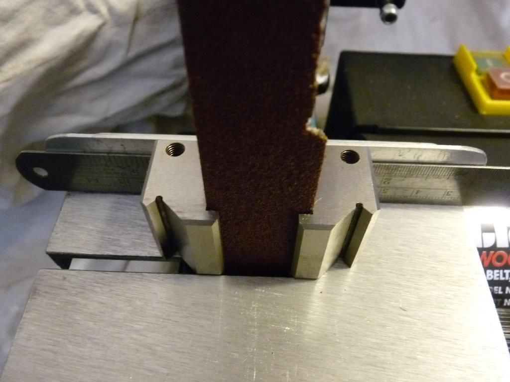
          I've just bought and modified a 1 inch linisher (from the big red and black tool-shed) to do the work (yes, the slot is 1 inch wide – how lucky is that) and so far have fettled the worst of my errent blocks so they now lock positively at <> 50% on the cam as per the original Bison blocks – result.

          The linisher, as bought, needed a thinner belt platten to get the belt into the quite narrow groove, a guide/stop and suitable shims were required to set the cutting depth. A little piece cut-out of the side of the belt was needed to feed the block into position. The resultant simple grinding procedure was done from both sides to reduce any potential error. I know that the slots are not absolutely true, but the blocks were essentially scrap and now they clamp-up very well. Fitting a new abrasive belt, now that I have fixed the worst offender(s), should improve the precision of the slot as lighter cuts will suffice on the remaining holders.

          linisher.jpg

          My ruler just happened to be the correct thickness to set the depth of cut for this holder.

          Based on potential savings over original Bison blocks, I'm quids in. Although I still wonder how manufacturers produce precision v groves to the tolerances shown above, but are unable to get the clamping slot anything like correct for a T00 QCTP, clone or otherwise. The worst case for me, needed the best part of 1 mm removed – the holder as delivered only just slid onto the block.

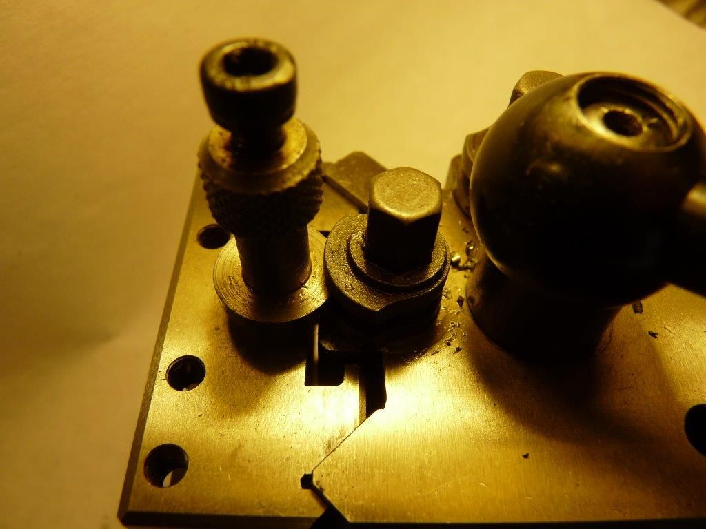
          50percent.jpg

          This is the holder that would only just slide into place – no locking action at all, now after grinding, a nice positive 50% lock position.

          Michael G's remarks on what are acceptable quality levels rings true – here I am, happily sorting out a very obvious manufacturing error, the distributor being unaware unless they follow the forum.

          When is a T00 QCTP not a T00 QCTP – when its a clone.

          Phil

          Edited By CotswoldsPhil on 28/12/2015 19:33:12

          #218208
          Clive Foster
          Participant
            @clivefoster55965

            Well done Phil. Really glad you have a good result by decently simple means. I'd probably have splashed out on a good carbide centre cutting end mill, machined down the back face to get a flat flange at the right position then screwed'n glued gauge plate flats on to make a new Tee slot with the clamping surface in the right plane. Tapping might have been a bear if the material was the near tools feel used on industrial rated holders.

            Round bars make it easy to check both the Vee spacing and parallelism of the Vee axes. Also work well to check that the clamping side of the T slot is parallel to the planes of the Vee. Would have put money on the error being due to planes of the Vees and T slot clamping plate being mutually out of parallel rather than the absolute dimension error you found. Out of parallel is the likely error if you get a bit careless with simple grinding set-ups. The dimensional error you found is basically not watching wheel wear so failing to make the necessary compensation. Which basically says the makers know that the production process is designed to produce out of specification parts and just don't care. A couple or three thou variation is plenty for finish grinding. 40 thou / 1 mm is beyond outrageous. Wonder how much error is on the Vees and how much on the T slot flange as wheel wear errors will be additive. In series production its always good if you can make tooling wear and other errors roughly opposite rather than additive so things tend to cancel out.

            Clive

            #218230
            CotswoldsPhil
            Participant
              @cotswoldsphil

              Morning Clive,

              It did not occur to me to check the 48mm at each end of the block / v to check for parallelism. I've still got the set-up so will take a peek. All very interesting this – I'm not a toolmaker, this is just a hobby for me.

              Regards

              Phil

              #218260
              Muzzer
              Participant
                @muzzer

                I made up a Dickson toolholder for my Bantam perhaps 18 months ago and used it as a DTI mount. It was as much to address the challenge of how to make it as address the need for one.

                If (like me) you intend to achieve the required vee features by using a standard milling cutter (4-flute end mill in my case), you may as well also measure it up with the body at 45 degrees. Otherwise you are measuring the vee dimensions and then having to translate them 45 degrees to the coordinate system used by the cutting process, using the square root of 2 many times.

                The vee features are clearly square (90 degrees) and are at 45 degrees to the front face. So, mounting the sample at 45 degrees, you can measure the (now horizontal) features and distances directly using a standard height gauge or in my case, using the DRO on the milling machine.

                Its perverse to measure the feature coordinates at one orientation and then translate them to another surely. A 3-axis DRO with a resolution of 0.01mm or so is ideal for acquiring the dimensions and also for implementing them on the workpiece. Theres no point making work for yourself.

                When I try to add an apostrophe, I end up with bizarre accents, graves etc. Some sort of Windows thing presumably.

                Murray

                #218269
                CotswoldsPhil
                Participant
                  @cotswoldsphil

                  Hi Muzzer,

                  I'm not intending to make any holders, my aim was to check the dimensions of the 11 commercial holders I have, 5 of which don't fit my tool-post at all because the clamping slot is too shallow. Checking the width of the V's was just a side-show and proved that any poor fit was not due to manufacturing errors in the V's.

                  The only metal I'm cutting is to increase the depth of the existing slot to make them usable i.e. able to clamp-up positively. With the set-up shown, I've been able to establish how much needs to be removed from each errant holder to get them to fit.

                  Regards

                  Phil

                  #218274
                  John Hinkley
                  Participant
                    @johnhinkley26699

                    I don't want to labour the point, but, before you go about re-machining or re-grinding the vees, have a close look at the clamps. My original ones didn't do the deed properly out of the box. I ended up making new ones with a (VERY slightly – like gnat's kneecap) thicker width to the clamping bit. (I'm sorry, I can't think of a better way to describe it!) That did the trick. The thicker clamp pulled the tool holder closer to the vees, bearing in mind the rather limited movement provided by the eccentric pin.

                    John

                    #218278
                    capnahab
                    Participant
                      @capnahab

                      Must make some Barry Jordan style carrousels to hold them sometime

                      Edited By KWIL on 24/12/2015 10:15:01

                      I am interested in the carousel toolholder, – anybody have any links / pics ?.

                      Cheers

                      #218306
                      CotswoldsPhil
                      Participant
                        @cotswoldsphil
                        Posted by John Hinkley on 29/12/2015 12:25:36:

                        I don't want to labour the point, but, before you go about re-machining or re-grinding the vees, have a close look at the clamps. My original ones didn't do the deed properly out of the box. I ended up making new ones with a (VERY slightly – like gnat's kneecap) thicker width to the clamping bit. (I'm sorry, I can't think of a better way to describe it!) That did the trick. The thicker clamp pulled the tool holder closer to the vees, bearing in mind the rather limited movement provided by the eccentric pin.

                        John

                        Hi John,

                        I have no intention of touching the V's. The are nicely ground and accurate as far as I can measure. All my measurements have been to establish how much to remove from the working face of each clamping-t-slot (all 5 are different and too tight) to allow the clamp to operate in its correct position, which seems to be the opposite of your situation. The original Bison holders are a perfect fit, so redoing the clamp is a non-starter, I would then have 2 Bison holders that are too loose. My aim was to have all my clone holders clamp to the same position as the Bison's.

                        If you take a look at the linisher set-up (a couple of posts back) you will see the method I have used to relieve the slots. I set the measured discrepancy with a shim, in this case 0.0315 inch (the worst one) and conveniently the thickness of my ruler, between the fence I made and the holder when the working-face of the slot was just touching the belt. Everything was set-up square beforehand – table / platten / fence / belt tracking. I removed the shim and linished away, until it all sparked out, having turned the block over about a couple of times to even out any potential errors.

                        I've just completed the rest of the holders this afternoon (much less metal to remove) and all is now well in my workshop, having 11 usable holders, instead of a pile of scrap.

                        Phil

                        #218308
                        John Hinkley
                        Participant
                          @johnhinkley26699

                          Phil,

                          Glad you got it all sorted. I obviously got the wrong end of the stick. Apologies. Happy to have solved my problem relatively easily, then.

                          All the best,

                          John

                          #218432
                          Bazyle
                          Participant
                            @bazyle

                            I mentioned earlier that I had bought a pack of 5 Soba holders from Chronos currently on offer quite cheap. I had only tried one so checked the others. All are 'tight' compared tot the old ones but one perversely only goes onto the boring tool position of the block and jams on the other side. Haven't worked out quite why but it shows there may be differences between the two clamping slugs. Must now do some measuring as per Phil's operation.

                            #218488
                            CotswoldsPhil
                            Participant
                              @cotswoldsphil

                              Hi Bazyle,

                              Well, well…

                              I was going to order a pack of 5 myself, fully expecting to fettle them as described above, looks like the linisher set-up will get some more use.

                              The 2 Soba holders I have (from a different source) are very well finished apart from a little edge breaking required on the tool slot.

                              Let me know how you get on – on my tool-post (Bison T00a) the difference between no clamp/tight as you describe, and nicely clamped is about 0.035 inch difference in the depth of the slot. Someone mentioned that a tolerance of 0.005 inch would be acceptable around a mean value for the tool-post. One holder which differs by 0.007 from the Bison clamps up very well, so I have left that be. Note: all my additional holders, except the one mentioned above, needed metal removed, I found none too loose.

                              I simply compared a well fitting holder (Bison original) to each clone holder to establish what had to be removed to make it fit.

                              Regards

                              Phil

                              Edited By CotswoldsPhil on 30/12/2015 14:05:50

                              #218715
                              CotswoldsPhil
                              Participant
                                @cotswoldsphil

                                A final bit of information (for those not bored silly) about the dimensions of the Bison QCTP and compatible holders.

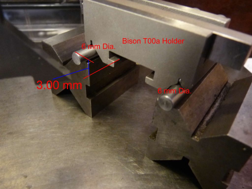
                                I decided (for reasons unknown) to rest an original Bison holder on 6 mm bars (instead of 1/4 inch as previous) to locate the bottom (working-face) of the t-slot relative to the V's. Working in metric, to my surprise, I got exactly 3.00 mm; is this a coincidence or designed?

                                tslotposition.jpg

                                Phil

                              Viewing 14 posts - 51 through 64 (of 64 total)
                              • Please log in to reply to this topic. Registering is free and easy using the links on the menu at the top of this page.

                              Latest Replies

                              Viewing 25 topics - 1 through 25 (of 25 total)
                              Viewing 25 topics - 1 through 25 (of 25 total)

                              View full reply list.