Clarke CL250M wiring

Clarke CL250M wiring

Home › Forums › Manual machine tools › Clarke CL250M wiring

Viewing 25 posts - 1 through 25 (of 28 total)
  • Author
    Posts
  • #834180
    Ian Mellors
    Participant
      @ianmellors72388

      I have just bought a second hand CL251MH milling attachment for my lathe, connected it up and thrown the switch to direct power to the mill motor and nothing.


      Before I start sending it back is there any way I can v

      Check my lathe is outputting correctly to the mill power socket at the back?


      I’ve looked online for a wiring diagram but can’t find one.


      The motor is 150w 220v dc brushed. The same as the lathe, which works fine.

      #834199
      Michael Gilligan
      Participant
        @michaelgilligan61133

        This may [or may not] help:

        https://www.clarkeservice.co.uk/manuals/metal_lathes/CL251MH_Mill_Drill_Attachment.pdf

        It appears, from p6, that it simply plugs into the socket on the lathe.

        MichaelG.

        .

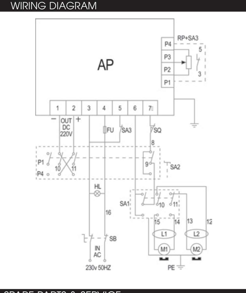
        Edit: a wiring diagram for the lathe is on p22 of this:

        https://www.clarkeservice.co.uk/manuals/metal_lathes/CL250M.pdf

        #834202
        not done it yet
        Participant
          @notdoneityet

          Do you have a multimeter to test out voltages and circuits?

          #834206
          Hollowpoint
          Participant
            @hollowpoint

            First thing to do is check the fuses. One in the plug socket and one on the mill head.

            #834212
            Michael Gilligan
            Participant
              @michaelgilligan61133

              Shame about the low resolution on that wiring diagram 🙁

              MichaelG.

              .

              IMG_1351

              #834232
              Ian Mellors
              Participant
                @ianmellors72388
                #834252
                Hollowpoint
                Participant
                  @hollowpoint

                  Sorry, yes. The fuse will be on the lathe somewhere.

                  #834254
                  Ian Mellors
                  Participant
                    @ianmellors72388
                    #834255
                    Hollowpoint
                    Participant
                      @hollowpoint

                      Do you have a lab type power supply? You could try putting say 30vdc directly to the mill head to see if it spins. At least you would then know if the motor is kaput.

                      #834257
                      Ian Mellors
                      Participant
                        @ianmellors72388
                        #834264
                        Hollowpoint
                        Participant
                          @hollowpoint

                          Not sure tbh. You probably need to be a bit closer to the motor specs. You may risk burning it out.

                          Does the motor have a plate or sticker on it showing the specs?

                          I know there is a sticker on the mill head but that is deceptive, because it shows the voltage and amps to the lathe, not the mill head motor. (I had this exact lathe/mill setup and also had problems).

                          A lab power supply is safer because most of them have multiple protection features.


                          #834272
                          Ian Mellors
                          Participant
                            @ianmellors72388
                            #834275
                            SillyOldDuffer
                            Moderator
                              @sillyoldduffer

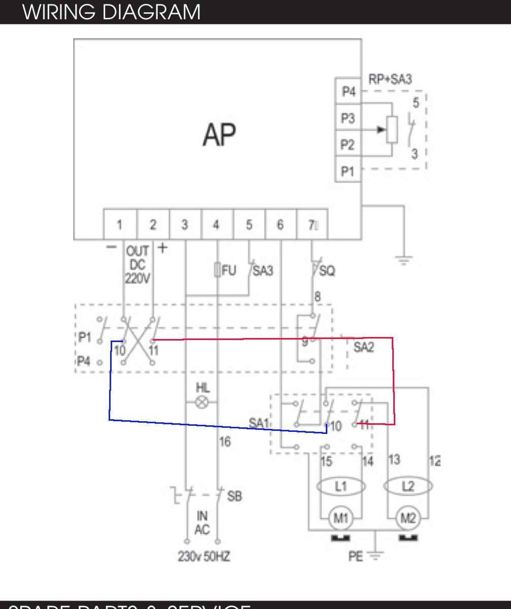
                              The circuit doesn’t show how power gets to the motors so I’ve added them, red + and blue – :

                              clarkcircuit


                              • Power comes out of terminals 1 and 2 on the AP Board
                              • DC + and – pass via reversing switch (P1 P4) to SA1
                              • SA1, has 3 switches, of which two (10, 11) are used to power either the lathe or the mill.  The circuit is very simple – mot much to go wrong.
                              • There are no fuses or safety cutouts between the power supply and motors.

                              Testing requires a multimeter.  Buy one, cheap will do, anything with a 200V-ish DC range.

                              Power On, if the lathe turns, the power supply is good and the fault lies elsewhere.

                              • The fuses must be OK, and, power must be reaching connectors 10 and 11 on switch SA1, and from there to the lathe motor. Otherwise the lathe wouldn’t turn.  Set speed to low, but ensure the motor spins.
                              • With the mill unplugged, set switch SA1 to the mill position (lathe should stop), and carefully probe the pins on the socket with the multimeter set to 200VDC or more.
                                • If needle moves then power is reaching the socket.   Therefore SA2 and the wiring to the socket is good.
                                • No needle movement means SA1 is faulty, or a connection broken, or the socket is fault.  Check for power on the socket terminals with the multimeter.  Look for loose connections etc.
                              • If power is available at the socket pins, gets more difficult.  Plug the mill in:
                                • Probe the motor to see if power is reaching it. If it is, the motor is the problem. Check brushes.
                                • If not, something wrong between socket and motor
                                  • the plug and socket may be a poor fit.   Depends on the design and how well made they are.  Might be as simple as splaying a split pin with a screwdriver so it makes contact.  Or cleaning corrosion.   Otherwise, replace both.
                                  • As the mill head is plugged in and out, the cable may have broken inside the plug, or less likely, fractured inside somewhere along the cable.   Replace plug and cable.

                              If the plug and socket are hard to find, there’s nothing special about them.  Any plug and socket that takes 200vdc will do.

                              Comment:  these mill-heads often fail, implying a design fault.  The motor, cable and plug are simple – nothing complicated in the head, so it should “just work”.  My guess is the plug and socket don’t stand-up to being plugged in and out or dislike vibration.  Not quite fit for purpose.

                              As usual, grateful if others review what I’ve suggested:  I may have missed something or misunderstood the circuit.

                              Good luck.

                              Dave

                              #834295
                              Michael Gilligan
                              Participant
                                @michaelgilligan61133

                                Well done, Dave

                                … I knew we could rely on you !

                                MichaelG.

                                #834316
                                Ian Mellors
                                Participant
                                  @ianmellors72388

                                  Thanks Dave, just seen this post.


                                  I have a fluke 77 DVM


                                  I have removed the brushes and continuity checked between the pins on the mill plug and the brass parts where the brushes connect to and it’s open circuit on both wires. surely there should be a connection?


                                  There is around 100v at the socket on the Lathe on the milling position.

                                  Plugs and sockets are standard IEC 3 pin

                                  #834319
                                  Ian Mellors
                                  Participant
                                    @ianmellors72388

                                    I can’t see how to get into the motor to check the wiring connections, there must be a way as the IEC plug on the other end is moulded on. The wire passes through a grommet at the base of the mill, up through the support tube and out the top before going into the motor. Unless there is a join somewhere the wire must be connected into the motor after threading through.

                                    #834320
                                    Ian Mellors
                                    Participant
                                      @ianmellors72388

                                      LOL


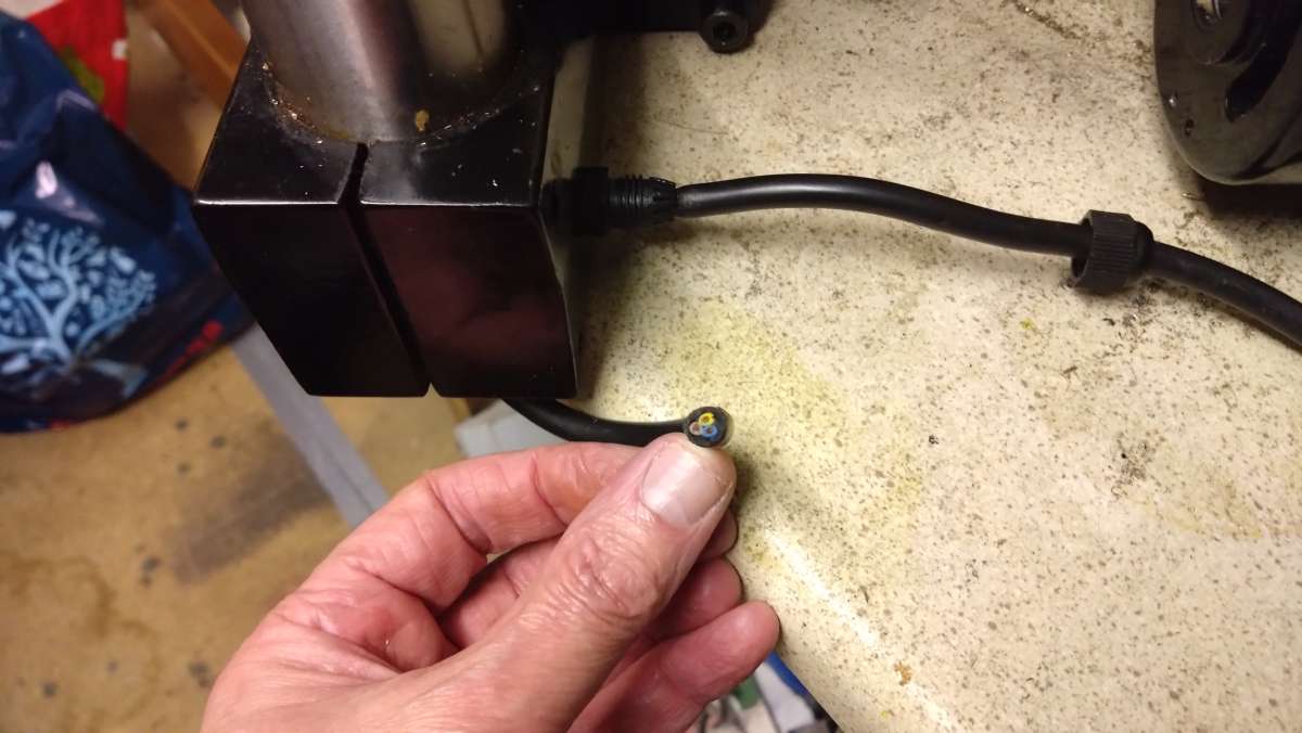
                                      DSC_0565

                                      That’s one hell of an insulation gap!


                                      Think I have found the problem 😉

                                      #834323
                                      SillyOldDuffer
                                      Moderator
                                        @sillyoldduffer
                                        #834325
                                        SillyOldDuffer
                                        Moderator
                                          @sillyoldduffer
                                          #834327
                                          Ian Mellors
                                          Participant
                                            @ianmellors72388

                                            one choccy block later (will make a more permanent solder/heatshrink join soon) and it all works as it should 🙂

                                            My guess it that someone tried to rotate the mill head out of the way by loosening the clamp bolts at the base and promptly guillotined the wire where it passes through quite a jagged hole in the tube.

                                            I will remember to loosen the top clamps and rotate just the head out of the way if I ever need to.

                                            #834328
                                            Ian Mellors
                                            Participant
                                              @ianmellors72388
                                              #834329
                                              John Haine
                                              Participant
                                                @johnhaine32865

                                                Yeah it’s mad isn’t it that it states 220v AC  when we all know it’s a DC motor

                                                It has to be an AC supply as the controller uses a triac to control the power. Triacs are 3 terminal devices which can be turned on by a pulse on their gate but not turned off  they rely on the current reversing to turn them off for the next cycle.  The triac controls for how long in each AC cycle power is applied.  The actual supply to the motor will go through a rectifier as it’s a DC motor.

                                                #834336
                                                Ian Mellors
                                                Participant
                                                  @ianmellors72388

                                                  Only thing left to do now apart from a good clean and oiling is to machine the end of an M6 cap head screw down to 4mm to make a new pin that retains the main gear shaft. If only I had a lathe….. 😉Untitled

                                                  #834348
                                                  Diogenes
                                                  Participant
                                                    @diogenes

                                                    Try searching ‘M6 Dog Point Grub Screw’ and see if that’s the thing..

                                                    #834652
                                                    Ian Mellors
                                                    Participant
                                                      @ianmellors72388

                                                      One thing I have noticed is that the mill seems to run the wrong way round. With the lathe switched in Forward, drills will be running the wrong way.

                                                      Has anyone else with one found this too? it’s no biggie to throw the revering switch, but it just grates with me. Before anyone asks, yes, I did connect the wires up blue to blue, brown to brown 😉

                                                    Viewing 25 posts - 1 through 25 (of 28 total)
                                                    • Please log in to reply to this topic. Registering is free and easy using the links on the menu at the top of this page.

                                                    Latest Replies

                                                    Home › Forums › Manual machine tools › Topics

                                                    Viewing 25 topics - 1 through 25 (of 25 total)
                                                    Viewing 25 topics - 1 through 25 (of 25 total)

                                                    View full reply list.