Off center groove

Off center groove

Home Forums Beginners questions Off center groove

Viewing 25 posts - 1 through 25 (of 26 total)
  • Author
    Posts
  • #216626
    Andrew Marr 1
    Participant
      @andrewmarr1

      Hi all, I'm new to the forum.

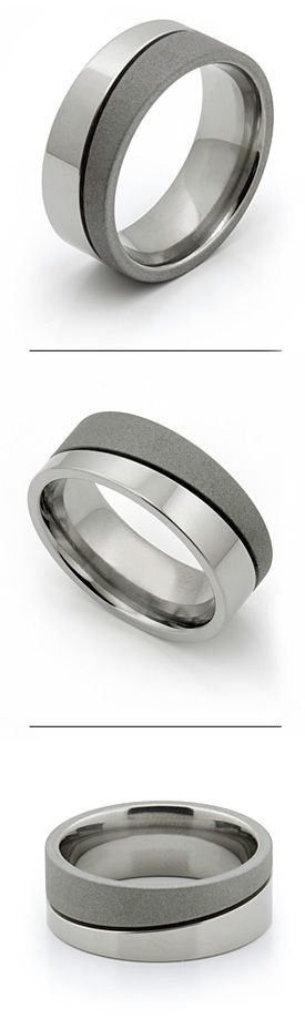
      I hope some one can shed some light on how to create an off center groove. I am trying to create the below ring. I have a Chester crusader lathe and also a Chester Champion 20v mill but cant seem to find an good way to hold the ring to run the groove in. The groove is at an angle of approx 16degs.

      Thanks in Advance.

      Cheers Andy

      sandblasted-ti-rings-720.jpg

      #7921
      Andrew Marr 1
      Participant
        @andrewmarr1
        #216659
        JasonB
        Moderator
          @jasonb

          Depending on how smooth running you want the groove I have seen it done using a rotary table and a set of co-ordinated generated from the CAD model. Basically a series of overlapping plunge cuts where you adjust the x-axis for each plunge. If I ever get round to it this will be the way I do part of the winding gear on my Ploughing engine.

          Most of the valve shuttles that I have seen with this type of groove (two actually) have been done with 4th axis CNC.

          #216667
          Martin Kyte
          Participant
            @martinkyte99762

            That's an interesting problem.

            Could you do it on the lathe with some arrangement of face contect cam on the spindle with a follower to the saddle then screw cut at a very slow speed?

            The cam only needs to be a bit of pipe sliced off at the correct angle.

            regards Martin

            #216669
            Martin Connelly
            Participant
              @martinconnelly55370

              Clamp it to a lathe faceplate with packing under one side to give the required angle. The clamping will need to be in the centre hole, you may need an intermediate plate with suitable threaded holes in it. If there are a number to be made make the intermediate plate into a jig. There will be a slight variation in depth of the groove due to the angle of the work piece. Centering will have to be done carefully as the od will not appear to be round when mounted at an angle.

              Martin

              Edited By Martin Connelly on 17/12/2015 09:05:48

              #216670
              pgk pgk
              Participant
                @pgkpgk17461

                How about fitting the ring to a mandrel, off-centre drilling each end then setting it up between centres to make the groove?? I'm not sure my spacial awareness is good enough to postulate whether the groove ends up even or some sort of elliptical depth…

                #216673
                jann west
                Participant
                  @jannwest71382

                  If you don't have 4 axis cnc, or too much time on your hands with a rotary table, make it in 3 pieces, glue it together (or solder if you're fancy).

                  Seriously … that's how the original was done. It's the easy way.

                  An offset workpiece between centres will give you an elipse, which will not have a uniform depth of groove (although at 16 degrees it's probably not that much out)

                  #216675
                  Chris Evans 6
                  Participant
                    @chrisevans6

                    As suggested I have done similar on a rotary table but only for grease grooves. The maths get a bit involved but in my case for grease to travel it was not fussy.

                    #216676
                    Martin Kyte
                    Participant
                      @martinkyte99762

                      You can't angle the workpiece if you want uniform depth.

                      Martin

                      #216687
                      Gary Wooding
                      Participant
                        @garywooding25363

                        It looks like a wedding ring made of two different metals. I would make each half separately and join them together afterwards. Each half could be turned on the lathe – each "external" end being a simple turning job on a stub mandrel. Each "internal" end would have to be machined on a stub mandrel that was at the required angle – like the picture. Making the mandrel will be interesting.

                        You can then join them together.

                        tilted mandrel.jpg

                        #216690
                        Hopper
                        Participant
                          @hopper

                          If you have a lathe with no backlash in the halfnuts (good luck with that one), all you need is a mechanism to rotate the leadscrew briefly in one direction , then the other., by the correct amount.

                          A simple crank mechanism or eccentric mechanism as used on steam engines comes to mind as the most common directional reversing mechanism.

                          You could, theoretically, drill a large change gear on the end of the leadscrew and press or screw in a crankpin as such.

                          Then do the same with a small change gear on the quadrant. Set this up so the small gears teeth do not engage with the leadscrew gear. But join the two crank pins together with a suitable length piiece of flat bar with two holes to fit the two crank pins. Gears would have to be arranged so the link bar is at a tangent to the PCD of the crankpin on the larger gear. So as the small gear rotates, driven by the train of gears from the mandrel, its motion is translated into a small back and forth motion of the leadscrew gear by the crank and link assembly.

                          Calculating the exact PCDs of the two crankpins and the geartrain to drive the smaller gear is a job for wiser heads than mine. I would probably just bodge about with a sliding crank pin assembly until I accidentally got it right.

                          But it seems, on further reflection, that the small gear would need to run at 1:1 with the mandrel. So the tool returns to the same point once per revolution. The PCD of the crankpin on the small gear would have to give the total 'stroke" to move the crankpin on the large gear back and forth by the amount you want the leadscrew to turn, which can be determined from the lead screw pitch and the amount of "lead" on the groove.

                          If the amount of movement is more than one revolution of the leadscrew, the crank mechanism would have to be on the mandrel end of the gear train and suitable gears used to increase the rotary movement the correct amount.


                          Edited By Hopper on 17/12/2015 12:42:50

                          #216692
                          pgk pgk
                          Participant
                            @pgkpgk17461
                            Posted by jann west on 17/12/2015 09:28:54:

                            If you don't have 4 axis cnc, or too much time on your hands with a rotary table, make it in 3 pieces, glue it together (or solder if you're fancy).

                            Seriously … that's how the original was done. It's the easy way.

                            An offset workpiece between centres will give you an elipse, which will not have a uniform depth of groove (although at 16 degrees it's probably not that much out)

                            As I thought… so perhaps a pointy cutter with a depth stop bearing each side and a push spring so it chases the groove to correct depth… a bit like router cutters?

                            #216695
                            Muzzer
                            Participant
                              @muzzer

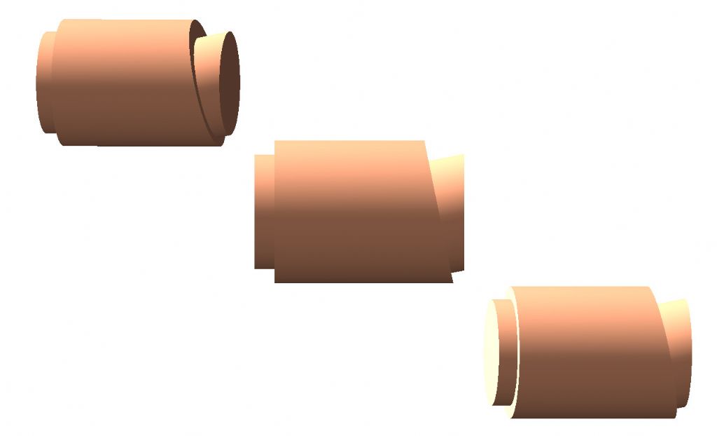
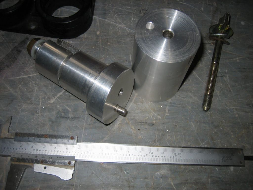
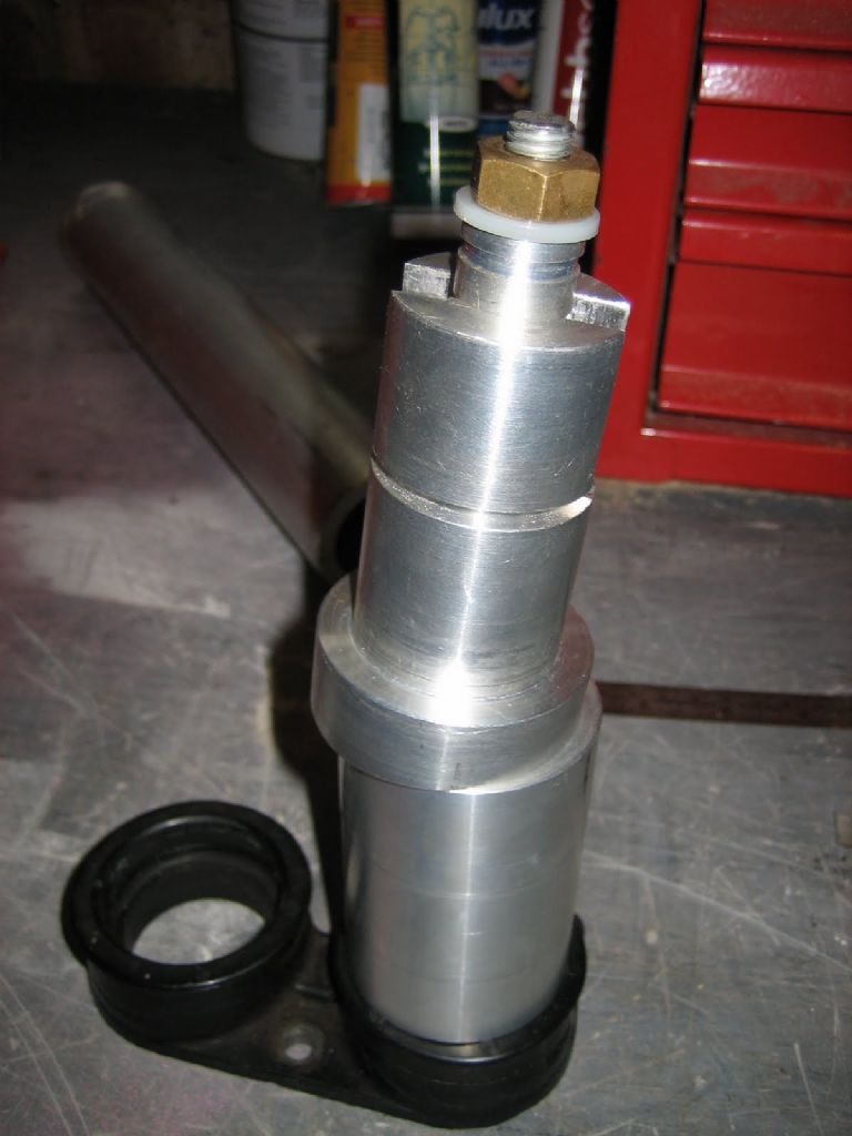
                              Something a bit like this?

                              Parts

                              Assembly

                              Making

                              Machine it so the work piece is concentric at the point you want the machined face.

                              Used this to make some inlet manifold adaptors to match some injector bodies to an inlet manifold with different, siamesed centres.

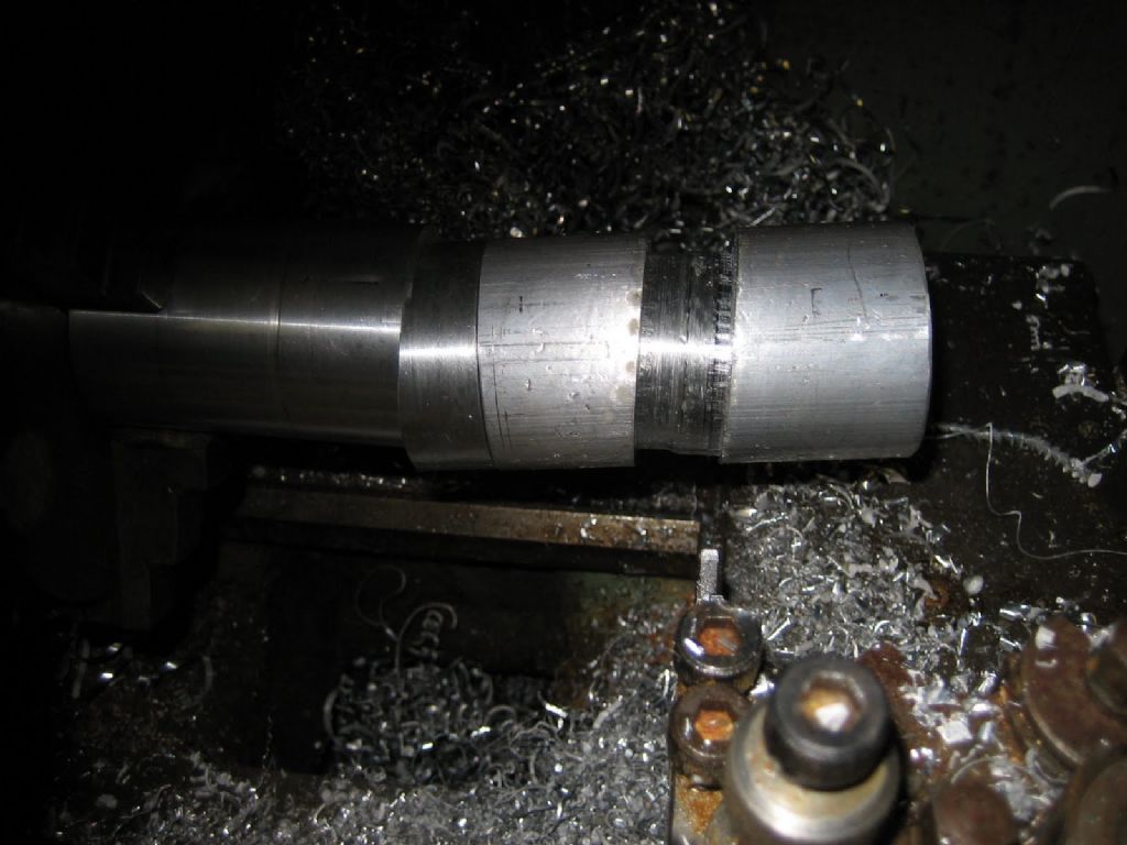
                              Worked OK but was a pain to make as you can see. Ideally you'd reduce the overhang more than I bothered to. And even more ideally you'd provide tailstock support.

                              In the trial in the bottom photo, the workpiece will be turned around so the cylindrical faces of both ends are parallel but offset.

                              Edited By Muzzer on 17/12/2015 13:34:23

                              #216699
                              Andrew Marr 1
                              Participant
                                @andrewmarr1

                                Hi all, Thanks for all the replies.

                                I should have said the material I am working with is Titanium grade 5. If I was to make the ring in 2 pieces I don't have any Ti tig wire to join it. It would also be a nightmare trying to weld on some thing that small.

                                Muzzer that jig looks like what I need. I tried to make a mandrel out of alloy bar with a 16deg angle milled on the top. I then tried to make a nylon bush to hold the ring but I could not get it to run on the axis. It would have cut a huge elliptical groove.

                                #216702
                                Gary Wooding
                                Participant
                                  @garywooding25363

                                  The reason I got into model engineering was the need to make tools for making jewellery. I would tackle your ring by hand-filing the groove after laying it out with a piercing saw. Use the depth of the saw blade as guide to the depth of the groove, then use suitable needle files to curve the edges. Ti isn't hard to saw or file.

                                  #216703
                                  Tim Stevens
                                  Participant
                                    @timstevens64731

                                    How about this:

                                    Take a thick-walled short tube of the material. Machine one end square to the original axis and machine the other end right across to the angle of offset of your groove.

                                    Set up on a faceplate using the chamfered end as location, and turn the groove. Turn the work round and set up on the squared face, cut off the chamfer, and turn the inner and outer diameters 'using a suitable tool' as Mr Haynes would say.

                                    A bit wasteful of material, but otherwise …?

                                    Regards

                                    Tim

                                    Edited By Tim Stevens on 17/12/2015 14:37:52

                                    #216710
                                    Gary Wooding
                                    Participant
                                      @garywooding25363

                                      The 16 degree angle of the groove means that its actually an ellipse.For an average sized ring (say 20mm ID) the depth of the groove, measured normal to ring's axis, varies by almost 0.4mm. In other words, the difference in length of the major and minor axes is about 0.8mm. That will make the width of the groove vary very obviously if the cutting tool isn't moved that much radially. Better to do it by hand.

                                      #216738
                                      frank brown
                                      Participant
                                        @frankbrown22225

                                        This like a lathe with a tracer on it except the pattern is wrapped around the chuck. so you make a band (16SWG MS) equal in length to the circumference of the chuck with a width of , say chuck depth and 2". Along one edge you plot out and cut one cycle of a sine wave with the maximum value of your peak displacement from the vertical of the groove (in both directions).

                                        Securely fix the pattern to the chuck edge. Set up a roller on an arm to engage on the edge of the pattern. Use a spring between the saddle and the tailstock to keep the saddle and its roller against the pattern. Set the lathe going at the minimum speed , or hand crank the spindle if nervous., the saddle should follow the pattern, feed in the tool .0001" at a time. Or replace the tool with a dremel type driven ball end cutter if you just want an oil groove.

                                        Frank

                                        #216739
                                        duncan webster 1
                                        Participant
                                          @duncanwebster1

                                          Frank's scheme but with a toolpost milling attachment would be even better. If you do use a fixed tool, I'd go for a bit more than 0.0001" at a time, or it could easily rub rather than cut

                                          #216853
                                          Gary Wooding
                                          Participant
                                            @garywooding25363

                                            You never mentioned if you're making a piece of jewellery, or something mechanical. If the former, then it seems like a great deal of work to make a pattern that fits sufficiently firmly on the chuck to withstand the considerable thrust needed to move the saddle of a Conquest lathe against a spring sufficiently strong to move it back again. Since you'll end up filing the pattern anyway, why not cut the groove by hand in the first place?

                                            Whatever route you take, you're going to have to do some careful filing. If you do the whole thing by hand, then when the filing is finished, the job is done. If you make a pattern, you also have to make a follower and make a suitably profiled cutting tool to cut the groove. Then cut the groove. For me, it's no contest – unless its for something that needs fine tolerances.

                                            There's a further consideration.The groove in your pictures has rounded edges. If you use a cutting tool in the lathe that also cuts the rounded edges, the groove will be correct at only two places round the ring; it will be lopsided everywhere else, you'll then have to file it to make it even. If the cutting tool doesn't cut the rounded edges, you'll have to file it anyway.

                                            #216921
                                            Andrew Marr 1
                                            Participant
                                              @andrewmarr1

                                              Hi Gary I am trying to create the ring that was pictured above.

                                              Looks like I have a few Ideas to try.

                                              I will attempt trying to file the groove in as you and few others said. I may try using a piercing saw. I think it will take a fair bit of time and patient but I will try masking the ring off first to try and get a good line to follow.

                                              #216951
                                              AndyP
                                              Participant
                                                @andyp13730

                                                Hi Andrew, I started machining metal for my jewellery business but have been sidetracked by steam engines!

                                                I have cut a groove like that in an 18ct white gold ring to inlay with yellow gold but the groove was probably wider than yours at 1.5mm. I did mine on a mandrel held in a chuck on my 6" Soba rotary table mounted on it's side on the table of my little X1 mill. I worked out the x displacement of the cutter for each 1 degree of rotation of the ring but can't for the life of me remember how! Then it was just a case of INC rather than CNC – that's Idiot Numerical Control.

                                                I have never machined Titanium so can't help there.

                                                Andy

                                                #216977
                                                Gary Wooding
                                                Participant
                                                  @garywooding25363

                                                  Hi Andrew,

                                                  To mark it out I would get a bit of pipe (copper, plastic, iron, whatever) with an ID suitable for boring out to accept the ring. Cut the end off at your required 16 degrees, insert the ring and follow the pipe end with the saw.

                                                  #217126
                                                  Gary Wooding
                                                  Participant
                                                    @garywooding25363

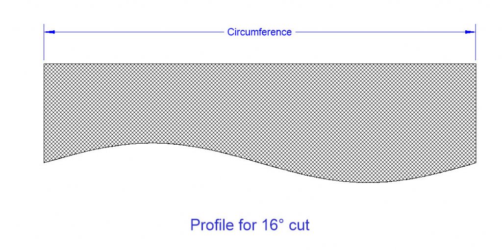
                                                    Instead of cutting a bit of tube, use the profile shown below. Reproduce it on a piece of paper scaled to the size you need, wrap it round the ring and follow the line. Its been calculated to give the required 16 degree angle.

                                                    16 degree profile.jpg

                                                    #217140
                                                    Andrew Marr 1
                                                    Participant
                                                      @andrewmarr1

                                                      Hi Gary thanks for doing this for me! Much appreciated.

                                                      I will try this when I come home from my next trip offshore, I go away on Monday for 22days oh the joys!

                                                      I will update on the results when I get back!

                                                      Thanks for all the comments and suggestions!

                                                      Happy Xmas and new year when it comes!

                                                    Viewing 25 posts - 1 through 25 (of 26 total)
                                                    • Please log in to reply to this topic. Registering is free and easy using the links on the menu at the top of this page.

                                                    Latest Replies

                                                    Home Forums Beginners questions Topics

                                                    Viewing 25 topics - 1 through 25 (of 25 total)
                                                    Viewing 25 topics - 1 through 25 (of 25 total)

                                                    View full reply list.