WARCO WM-250 thread dial

WARCO WM-250 thread dial

Home Forums Workshop Tools and Tooling WARCO WM-250 thread dial

Viewing 17 posts - 1 through 17 (of 17 total)
  • Author
    Posts
  • #18088
    Martin Botting 2
    Participant
      @martinbotting2

      Dial indicators that go bump in the night.

      #237814
      Martin Botting 2
      Participant
        @martinbotting2

        Having installed the Warco 250vf and eager to play I thought time to use the whining wheels and carriage mover part and cut a thread, I followed the destruction of whats wheels go where and tore up the invoice to set the backlash in the gear train a touch of chain lube and away we go…. Ah… the thread dial is not turning, its not in mesh… allen key adjust start again… CLUNK CLUNK CLUNK…. hit the big red button!

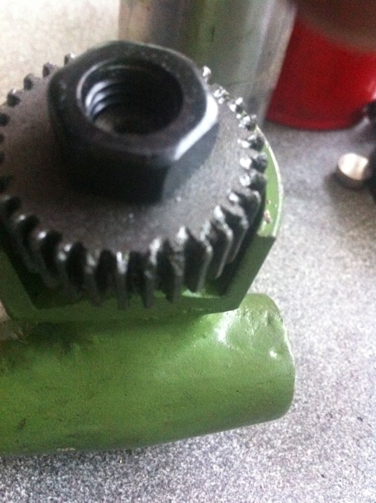
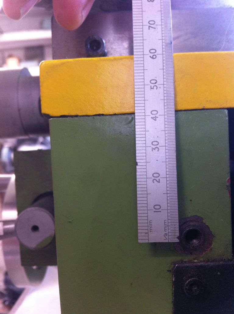
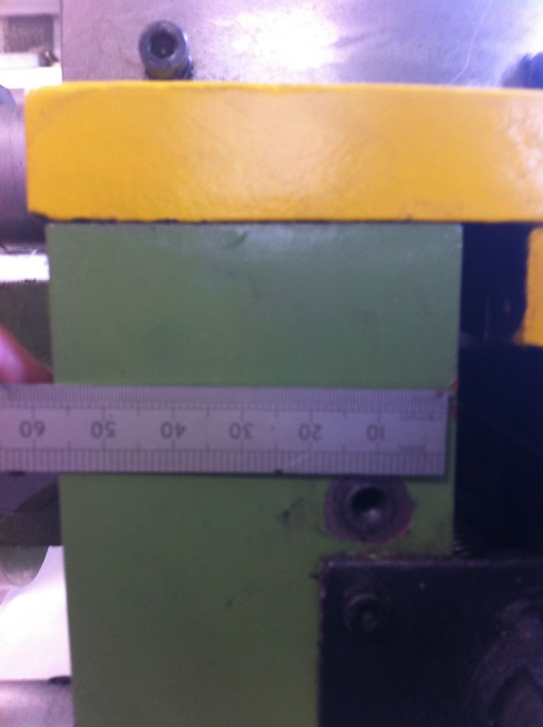
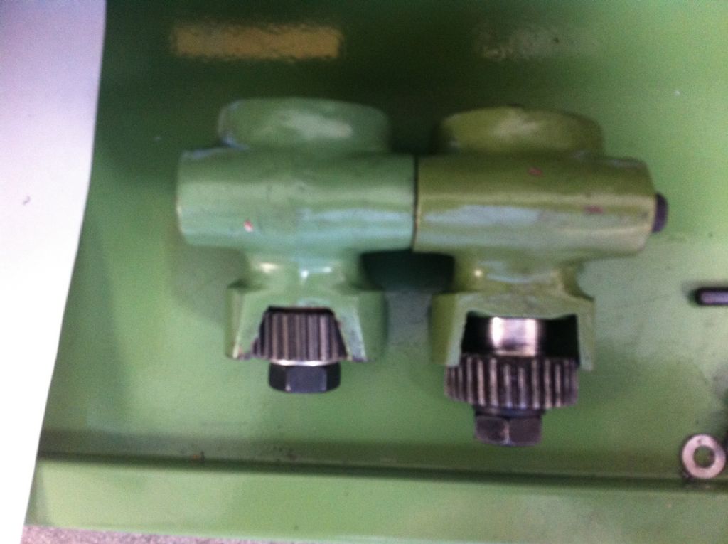
        It would seem the drive gear is just kissing the lead screw and the milled keyway is hitting the teeth, did some investigations and the gear is riding miles too high above the centre line of the leadscrew. I took it all apart and there is no damage to the leadscrew but the fixing screw is bent and the ends of the teeth on the drive screw have been mauled, I contacted the service dept of warco and a very helpful gent has sent a replacement unit I fitted it tonight and its the same. Now my way of thinking is this, the fixing for it is too high up the apron body as the two castings are the same size I have thought about machining a new shaft to lower the gear into a better mesh. I wonder do any other WM250 owners have this issue? and could anyone have a measure up and see where there mounting holes are. I will add some pictures Any ideas or help please folks.

        PS the replacement dial Warco sent has 6 numbers on the face the one as fitted has 4, the lathe is the imperial version.

        Martin

        #237815
        Martin Botting 2
        Participant
          @martinbotting2

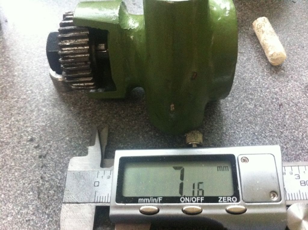
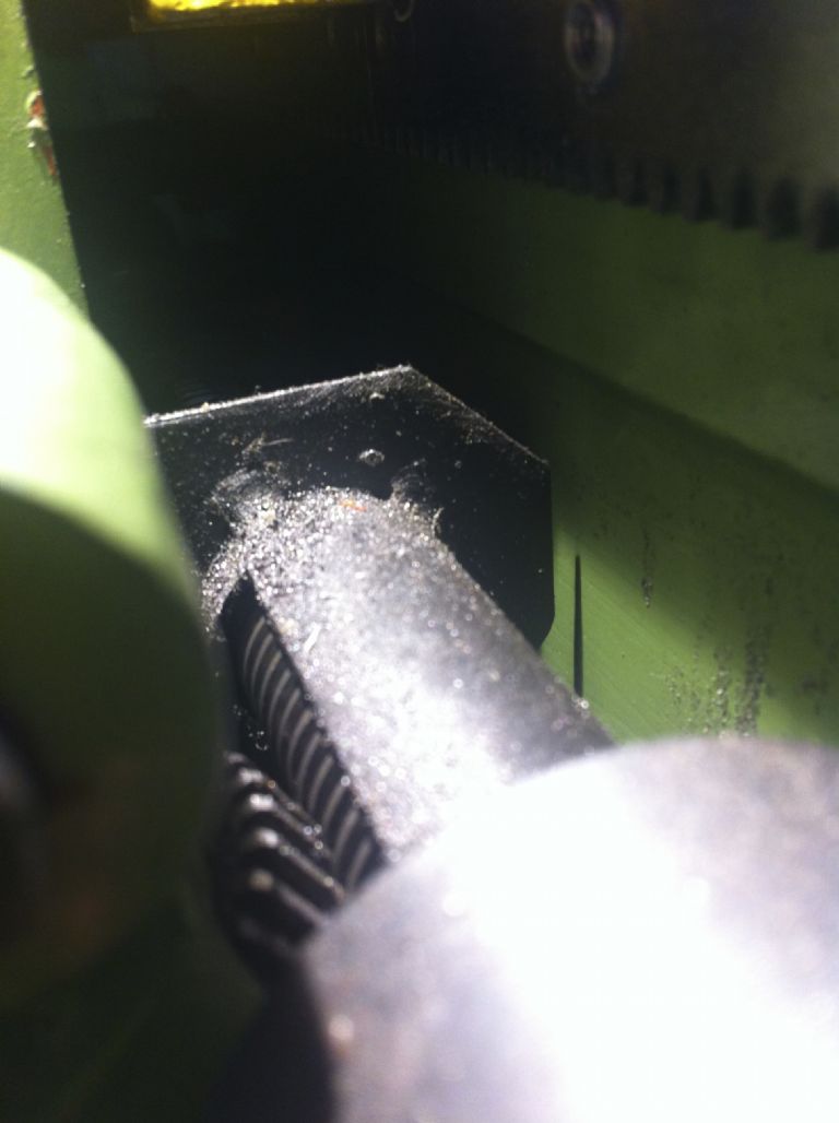
          img_2271.jpgimg_2268.jpgimg_2266.jpgimg_2260.jpg

          #237862
          mechman48
          Participant
            @mechman48

            Martin FWIW… I have taken a couple of pic for your att. from my 250V-F … It is possible that the bracket on your machine may well be a different machine fitting, poss' a 180 or 240… dont know

            Dial as supplied…

            screwcutting dial (4).jpg

            Screw cutting dial gear in mesh…

            screwcutting dial (1).jpg

            Bracket fixing distance…

            screwcutting dial (2).jpg

            Bracket length…

            screwcutting dial brkt (1).jpg

            Gear gap compared to yours…

            screwcutting dial brkt (2).jpg

            It looks as though on your pic 3 the gear needs to go back further on the shaft…is this as supplied or have you had the gear off the shaft before writing your post.

            George.

            #237888
            Martin W
            Participant
              @martinw

              Martin, as George has said, it appears that the gear is not far enough on the shaft, looking at your second picture the securing nut is barely engaging on the threaded shaft. The gear and shaft are held in register with a key and each has a keyway cut into them. I am wondering if you have aligned the parts correctly to get correct engagement or is the gear just sitting on the end of the key. If so then this could cause the gear to sit too low and hence there is not enough thread to engage the locking nut properly.

              Sorry if the above sounds a bit cumbersome.

              Martin W

              edit; Looking at your picture 3 you can clearly see the key set in the shaft. This should be fully engaged with the gear wheel and should not be visible. I suspect that this is causing your problem. 

              2nd edit; If as you say the gear is riding too high to engage the lead screw then moving the gear further onto the shaft is not going to help, in fact it would appear that it would make the problem worse.

              Edited By Martin W on 07/05/2016 18:36:47

              Edited By Martin W on 07/05/2016 18:49:37

              #237889
              Martin Botting 2
              Participant
                @martinbotting2

                Gents. thanks for the comments thus far. The gap and the nut just on is how far down the shaft I have had to let the gear drop to get it to sit on the centre line of the lead screw.

                #237890
                Martin W
                Participant
                  @martinw

                  Martin how do the measurements supplied by George compare to the mounting points on your lathe and the thread dial assembly?

                  Martin

                  #237892
                  Martin Botting 2
                  Participant
                    @martinbotting2

                    George.

                    I took the gear off to have a look at it and try lowering it so it would sit on the leadscew much like your one. I will get busy with the scale and some head scratching in the morning and the church of swarf.

                    Posted by mechman48 on 07/05/2016 14:00:32:

                    Martin FWIW… I have taken a couple of pic for your att. from my 250V-F … It is possible that the bracket on your machine may well be a different machine fitting, poss' a 180 or 240… dont know

                    Dial as supplied…

                    screwcutting dial (4).jpg

                    Screw cutting dial gear in mesh…

                    screwcutting dial (1).jpg

                    Bracket fixing distance…

                    screwcutting dial (2).jpg

                    Bracket length…

                    screwcutting dial brkt (1).jpg

                    Gear gap compared to yours…

                    screwcutting dial brkt (2).jpg

                    It looks as though on your pic 3 the gear needs to go back further on the shaft…is this as supplied or have you had the gear off the shaft before writing your post.

                    George.

                    #238395
                    Martin Botting 2
                    Participant
                      @martinbotting2

                      Posted by mechman48 on 07/05/2016 14:00:32:

                      Martin FWIW… I have taken a couple of pic for your att. from my 250V-F … It is possible that the bracket on your machine may well be a different machine fitting, poss' a 180 or 240… dont know

                      Dial as supplied…

                      screwcutting dial (4).jpg

                      Screw cutting dial gear in mesh…

                      screwcutting dial (1).jpg

                      Bracket fixing distance…

                      screwcutting dial (2).jpg

                      Bracket length…

                      screwcutting dial brkt (1).jpg

                      Gear gap compared to yours…

                      screwcutting dial brkt (2).jpg

                      It looks as though on your pic 3 the gear needs to go back further on the shaft…is this as supplied or have you had the gear off the shaft before writing your post.

                      George.

                      George.

                      the measurements seem the same img_2324.jpg

                      #238396
                      Martin Botting 2
                      Participant
                        @martinbotting2
                        img_2325.jpgPosted by Martin W on 07/05/2016 18:58:30:

                        Martin how do the measurements supplied by George compare to the mounting points on your lathe and the thread dial assembly?

                        Martin

                        Much the same. Martin, img_2324.jpg

                        #238397
                        Martin Botting 2
                        Participant
                          @martinbotting2

                          So to continue the saga of bangs and clunks… Peter at Warco sent out a new threading dial and I tried it and guess what…. CLUNK CLUNK CLUNK… So better get this sorted I machined up a new shaft for the dial and made up a bushing to keep it from dancing about the gear now rides the lead screw on its middle line so the keyway does knock the granny out of the teeth and vicky versa. I have packed up the replacement dial and its on its way back to Warco, Tell me from the pictures posted by George on this thread and the replacement dial there are far more marks on the dial face is that important or just more chances at starting?

                          I have added these pictures to show the fix, I hope this won't invalidate any warrantee! I would hate to have to walk home from the makers with a bent lead screw on my shoulder. img_2317.jpg

                          #238407
                          Martin W
                          Participant
                            @martinw

                            Martin

                            Looking at the pictures between your lathe and Georges there is a difference in the alignment of the lead screw cover fitting. On yours the fitting screw is almost vertically aligned with the Thread Dial mounting hole whereas on Georges there is a significant offset. If the lead screw cover is the same then the lead screw has been moved relative to the apron on the saddle. in fact it now would be further away and could cause the problem that you are experiencing. I am wondering if WARCO have had a change of design or manufacturer and not updated the Thread Counting Dial to reflect the change.

                            It doesn't help your problem but it may be worth raising with WARCO.

                            Cheers

                            Martin W

                            #238415
                            JasonB
                            Moderator
                              @jasonb

                              The different numbers on the dial could be the difference between a metric and imperial one, did you check to see if the gears were the same number teeth?

                              #238425
                              Martin Botting 2
                              Participant
                                @martinbotting2

                                Martin

                                I have just noticed that well done. It had skittered over the old grey matter a while back if the lead screw was set back.

                                I will give warco a call

                                Martin B

                                Posted by Martin W on 12/05/2016 12:02:47:

                                Martin

                                Looking at the pictures between your lathe and Georges there is a difference in the alignment of the lead screw cover fitting. On yours the fitting screw is almost vertically aligned with the Thread Dial mounting hole whereas on Georges there is a significant offset. If the lead screw cover is the same then the lead screw has been moved relative to the apron on the saddle. in fact it now would be further away and could cause the problem that you are experiencing. I am wondering if WARCO have had a change of design or manufacturer and not updated the Thread Counting Dial to reflect the change.

                                It doesn't help your problem but it may be worth raising with WARCO.

                                Cheers

                                Martin W

                                #238426
                                Martin Botting 2
                                Participant
                                  @martinbotting2

                                  Jason, I have counted the teeth on the one I have and thats 30 tooth, when i get home i will have a count of the warco replacement.

                                  Still trying to get my feeble mind around how the numbers work on that and the maths issue of the change wheels.

                                  #238431
                                  mechman48
                                  Participant
                                    @mechman48

                                    Martin W…

                                    I reckon you're on to something there…

                                    'Tell me from the pictures posted by George on this thread and the replacement dial there are far more marks on the dial face is that important or just more chances at starting?'

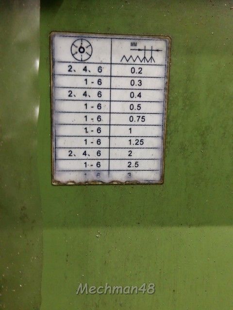
                                    Martin B … Judging by the TPI chart numbered 1 – 6, I make the assumption that you should be able to pick up threading on any number diametrically opposite ea. other to get the same TPI ,instead of waiting for the dial to come round again…

                                    tpi scale.jpg

                                    i.e. … 1 – 7, 2 – 8, 3 – 9, 4 – 10 etc.

                                    screwcutting dial (4).jpg

                                    Not having done any single point…yet … always used the tailstock die holder for the small amounts I've done; so I am making the assumption…

                                    leadscrew centre.jpg

                                    As an after thought… check the positioning of your leadscrew centre, may be the design has been altered…

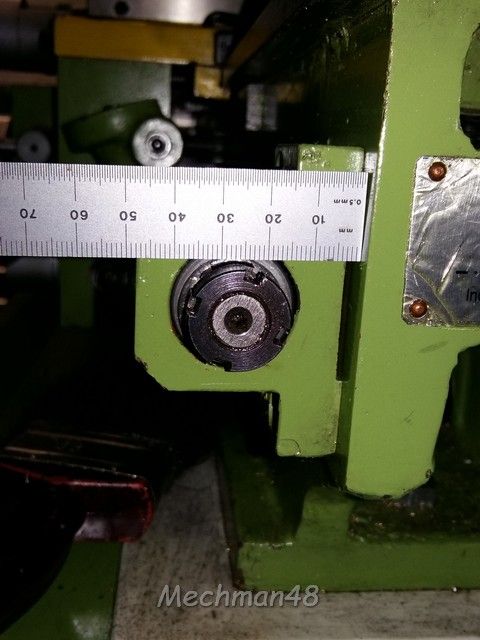
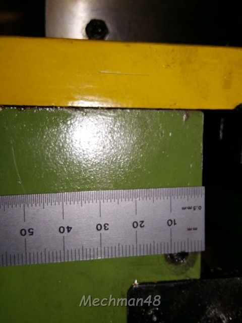
                                    I might have sussed it, took some more measurements…take into account camera parallax error… your hole centre looks approx 11 – 12mm from the edge of your saddle… mine is 6 – 7 mm from the edge of my saddle, a difference of 5 -6 mm… voila! your radius of arc is greater than mine hence your gear will swing further round than mine hence contacting on the bottom of the gear not on centre line… if you get my drift, …solution … plug the original hole & redrill approx' 6mm closer to the edge of your saddle. I know you've already resolved it so to speak with the spacer but…

                                    lathe dimensions (4).jpg

                                    George.

                                    #238459
                                    Martin Botting 2
                                    Participant
                                      @martinbotting2

                                      George the centre of the leadscrew is about 26mm from the lathe bed casting. the move of the swing point is probably the thing. BY George you have got it!

                                      Praps mine was built on a friday and the fitter was making for the door when he laid out the centre dot for the driller and was in a hurry to catch the tram home.

                                    Viewing 17 posts - 1 through 17 (of 17 total)
                                    • Please log in to reply to this topic. Registering is free and easy using the links on the menu at the top of this page.

                                    Latest Replies

                                    Viewing 25 topics - 1 through 25 (of 25 total)
                                    Viewing 25 topics - 1 through 25 (of 25 total)

                                    View full reply list.