Strange Transparency?

Strange Transparency?

Home Forums CAD – Technical drawing & design Strange Transparency?

Viewing 20 posts - 1 through 20 (of 20 total)
  • Author
    Posts
  • #831897
    Nigel Graham 2
    Participant
      @nigelgraham2

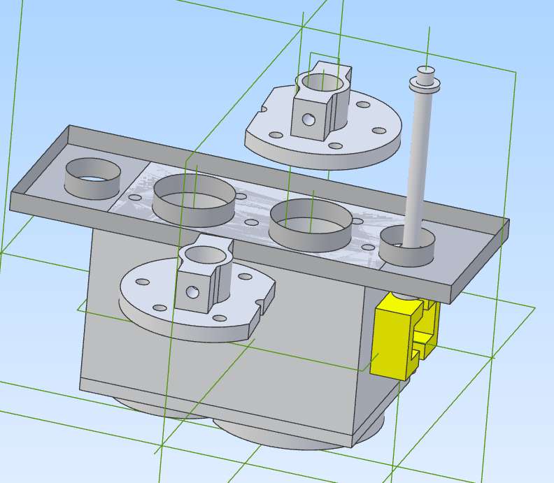
      I’ve examined the appropriate Part model and its Assembly, the Colour menu shows 100% Opacity, but what’s happened to the central plate, please?


      An edit after going back for another look, and found:

      Even odder, if I flip the assembly over the plate looks solid. I can’t pick up the external surface to constrain the covers to it. It acts as a very thin translucent tray with two hollow cylinders glued to it! So the constraint tool can only find the inner surface (against the cylinder block).


      It not only looks peculiar. It’s making it very confusing to build up!

      I should add I’d been trying to modify the bolt-holes in the Assembly, having found how to do that from the manual. It does say it will make parts translucent but I’d not expected that to stay afterwards without showing.


      Screenshot 2026-01-09 172821

      #831908
      JasonB
      Moderator
        @jasonb

        Have you clicked “shell” by any chance? but unlikely to give that lighter area where the plate meets the block but it will give that “tray” look.

        Have you clicked save after your edit as the plate may still be editable though again it is usually the other parts that go transparent and the one being edited solid.

        #831910
        David Jupp
        Participant
          @davidjupp51506

          The light area where tray meets block is because the parts interfere slightly.

          As Jason mentioned, it does look like a Shell has been performed.  Open the part and check the Design Explorer for any Shell, if there is one suppress it.

          Check also that the part has been fully regenerated, i.e. the blue dog bone is at the bottom of the list of operations.

          #831911
          Nigel Bennett
          Participant
            @nigelbennett69913

            Have you contrived to make just the surface transparent?

            #831912
            David Jupp
            Participant
              @davidjupp51506
              On Nigel Bennett Said:

              Have you contrived to make just the surface transparent?

              No – that isn’t possible in Atom3D.  It is a solid modeller, doesn’t do surfaces.

              #831913
              David Jupp
              Participant
                @davidjupp51506

                Nigel – as always, if you send the part file of the plate I can tell you what has happened (unless it’s some odd graphics system issue).

                #831914
                Fulmen
                Participant
                  @fulmen

                  Never used Atom but I’ve seen glitches like that in other software. Often it’s some small error like a missing dependency or it’s over constrained somehow. You can start by saving into a new file and restart the software.

                  #831924
                  Nigel Graham 2
                  Participant
                    @nigelgraham2

                    Thankyou.

                    I have examined both the Part and the Assembly.

                    No “Shell” command in either file, and the plate is shown correctly in its own file.

                    Fully regenerated.

                    I have closed the model and indeed Alibre two or three times since this happened earlier today, so would have expected the assembly to have caught up as it does in normal use.


                    I’ll send both the Part and the Assembly, because I’ve no idea which one holds the fault.

                    I can only think I’ve made some mistake trying to modify the plate from within the assembly, because I wanted the rings of holes to match; but the “shell” effect only appeared some time later.


                    Fulmen –

                    Alibre Atom tells you if over-constrain anything, but its “constraints” fit 2D sketch elements and assembly Parts to each other, not control their renderings. Other CAD systems may have different definitions, of course. I don’t know what a “dependency” might be in Alibre Atom, if an equivalent exists. Perhaps hidden within constraints’ maths rather than an operating tool.

                    #831925
                    Peter Cook 6
                    Participant
                      @petercook6

                      I don’t use Atom, but I get the same effect in MoI if the top face of the main block is in the same plane as the top face of the tray, i.e. the two surfaces ( top of the block and top of the tray are co-planar). I would have expected the top of the block to be co planar with the bottom of the tray – i.e. the tray has thickness.

                      If the bottom of the tray is a simple plane – i.e it has no thickness, I would expect to see this.

                      #831927
                      blowlamp
                      Participant
                        @blowlamp

                        Maybe it’s some kind of display glitch. It looks like the top surface of the plate is missing and the mixed-shaded area looks much like ‘Z-fighting’, where two surfaces occupy the same plane and the CAD can’t decide which surface to display, although even that is a bit odd because the shaded area doesn’t align with the block, but it does appear to be of the correct length.


                        Martin.

                        #831933
                        Charles Lamont
                        Participant
                          @charleslamont71117

                          No idea about Alibre, but Onshape has a similar appearance when two bodies are on the same side of coincident surfaces, as Peter says.

                          #831937
                          JasonB
                          Moderator
                            @jasonb

                            Peter/Charles. Alibre would just show it in the solid grey if the two surface sare coincident. Even the inside of a tray if coincident with thetop of the block comes out solid. I did try to replicate it and can easily get the hollow “Tray” using shellbut not the patchy surface

                            Nigel, out of interest how did you position the plate on the block did you use “component placement” and just drag it there or use constraints?

                            #831938
                            Nigel Graham 2
                            Participant
                              @nigelgraham2

                              It was a very strange effect.

                              No, I used constraints to put the parts together. I know simply dragging one to the other won’t work, and will leave either a small gap or one melting into the other.


                              Normally if I want to modify a part I save and close the assembly, re-open the part and edit that, save and close that; then re-opening the assembly brings the modification in without problems.


                              This though was something else. I’ve used the opacity setting to examine parts hidden behind another, but that peculiar “shell” effect was very different even from that.

                              I’ve only used the Shell tool once, mainly to find what it does, but know it asks for settings so cannot see how it can create a hollowed-out effect all by itself. I examined the tool-bar to see if I could select it by mistake but it seems to far from the other extrusion types. Anyway, since it stops and asks for instructions I think I would have noticed it in time.


                              All I can think is that after I had edited the plate within the assembly, when the process does make it transparent, it did not return to being solid. I returned to the instruction manual to see if I had missed something. It tells us:

                              .. Open a Part or Subassembly for Editing in the Context of an Assembly


                              Right-click a part in the assembly Work Area or the Design Explorer, and select the Edit Here command.


                              If a part is selected, the workspace will change to provide feature and sketch tools, similar to being in a part workspace.


                              If a subassembly is selected then the subassembly will expand to show all information about the subassembly and the Design Explorer will behave as if the subassembly was the root assembly. The text for the part or subassembly in the Design Explorer will become blue to indicate that it is being edited.


                              While editing a part in the assembly context, other assembly components will become semi-transparent but can still be used for reference as well as measurement purposes.


                              It was the Part within an Assembly I’d selected. I wonder if I’d gone wrong there somehow, perhaps picked the wrong instructions, so it had taken at least two separate sessions of using Alibre as a whole for the files to close and re-open properly.

                              Ironically, I decided the modifications would not help as I’d thought, and restored the original.

                              #831940
                              JasonB
                              Moderator
                                @jasonb

                                Alibre will shell to the default setting without you having to enter a thickness which is quite thin so maybe why we can’t see a thickness to the top edges of the tray and would only show if the image were zoomed in

                                #831941
                                David Jupp
                                Participant
                                  @davidjupp51506

                                  Nigel sent me the part file – and a message that the rendering issue had self-resolved.  The part looks fine on my system.

                                  My guess is a temporary graphics glitch which needed  a reset of the software (or possibly the computer) to resolve.

                                  I’ll check the assembly when I get the balance of files from Nigel.

                                  #832123
                                  Nigel Graham 2
                                  Participant
                                    @nigelgraham2

                                    I’ve now saved the Assembly in Package form and sent it.


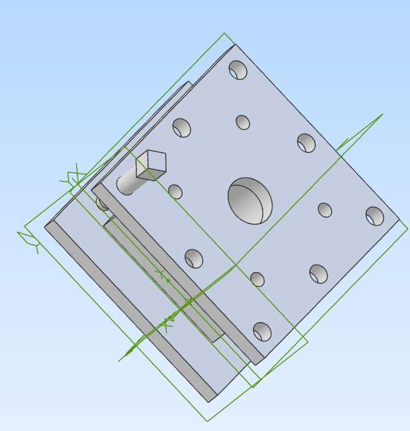
                                    As a test, I created the simple 4-way Tool-post below to see if the transparency problem would recur. It didn’t.


                                    The central block is sandwiched by two plates with countersunk or counter-bored screws, omitting the last details of the holes.

                                    I could have modelled one plate as two extrusions: outline with central spindle hole and the four assembly screw-holes as extrusion 1, edit copies of that Part to “make” the other two, then add the tool-clamp screw holes in one plate only by extrusion 2.

                                    Here I wanted to use the same principle as in the cylinder block.

                                    Try spotting the screw-holes right through the block and lower plate by editing the top as a part in place, with the central block and lower plate un-drilled.

                                    “Extrude Cut – through all” from the top plate obligingly drilled the two other components to match, and the transparency lasted only as long as I was editing the assembly.


                                    As I’d hoped.


                                    In practice the first method (editing copies) may be more efficient for something this simple, but I wanted to try the part-in-place editing.

                                    I’d only just guessed CAD should let me do things like that, otherwise adding or modifying matching features sprung from one component to another, such as bolt-holes, would entail editing each affected part or even plotting patterned features twice. As I had been doing! Very inefficient, with potentially mis-quoted dimensions. Been there too.

                                    (The old manual methods included drawing the second part on tracing film over the drawing of the first.)

                                    When I model screw-hole pairs with one tapped, as on this tool-post, sometimes I draw both to clearance size and notate the eventual drawing’s thread identity. The difference on a small thread is not really visible on the printed drawing anyway.

                                    Screenshot 2026-01-11 173454

                                    #833167
                                    Nigel Graham 2
                                    Participant
                                      @nigelgraham2

                                      The “tray” effect occurred again a couple of days ago, and this time with a part still floating in thin air, not assmebled to another.

                                      So most likely a peculiar hiccup in the software somewhere, if not in Alibre Atom as installed on my PC then in the background graphics generator.

                                      It hampers making assemblies when I can’t see the surface I want. The Shell tool is too far along the tool-bar to select it by mistake, unlikje the New Part one which is right next to Insert Design.

                                      The effect is unusual and seems to be cured by a couple of one/off iterations, so I can probably live with it unless it really starts to happen often and becomes harder to clear.

                                      I have many photographs on the computer but don’t use it for other image processing including photo-faffers, as a TV and hardly ever for TurboCAD in 3D mode.

                                      So I have seen it happen only in Alibre Atom, but now twice, so it is easy to think my local installation of it has developed an intermittent fault. If it does start to become a real problem I may have to consult a computer repairer to find if the fault is within the computer generally.

                                      …..

                                      By the way, if I do pick accidentally “New part” instead of “Insert design”, is there a direct return to the normal Assembly screen? The move turns off the “Redo” arrow so you can’t use that. I’m having to save and close the work and re-open it to return, which doesn’t seem right.

                                      #833171
                                      David Jupp
                                      Participant
                                        @davidjupp51506

                                        Nigel;

                                        If you select New Part by accident you need to return to editing the assembly, either by

                                        • right click on New Part in the Design Explorer -> choose ‘Edit root assembly’
                                        • right click on the Assembly right at top of Design Explorer -> choose ‘Edit Part/SubAssembly

                                        Having done that you can select the accidental New Part in the Design Explorer and press the Delete key.  That will get rid of the accidental part.


                                        As for graphics glitches – update graphics driver if a newer one is available.  If you have the latest one already, try rolling back to a previous one to see if it is more stable.

                                        IF your graphics adapter supports it – make sure that hardware accelerated graphics scheduling is enabled in Windows.

                                        There is a ‘Customise Performance’ option in Atom3D – try turning off all the fancy graphics effects, that should give your graphics adapter an easier time.   Make sure that ‘Hide small faces’ and ‘Delay small face render’ are not enabled – these can cause faces to vanish if below the threshold.


                                        The Intel UHD 630 is not a great adapter for 3D graphics, but should manage basic stuff.  If you are hitting problems as the assembly gets more complex, it may be time to consider a dedicated graphics card, rather than an integrated one.

                                        #833175
                                        SillyOldDuffer
                                        Moderator
                                          @sillyoldduffer
                                          On Nigel Graham 2 Said:

                                          The “tray” effect occurred again a couple of days ago, and this time with a part still floating in thin air, not assmebled to another.

                                          So most likely a peculiar hiccup in the software somewhere, if not in Alibre Atom as installed on my PC then in the background graphics generator.

                                          Though not impossible, unlikely Alibre, the Graphics System or your installation is faulty.   I’ve seen similar effects in SolidEdge and Fusion360 when two parts overlap in space.  It means the model is incorrect.  Usual cause is missing or conflicting constraints.   In the real world parts can’t occupy the same space without bashing them with a big hammer.   Although CAD allows parts to overlap temporarily in virtual space, it can’t render the result properly, and of course the model is broken, causing more trouble later.

                                          Constraining such parts correctly fixes it for me.   Not always obvious what’s wrong.  Whilst missing constraints are usually easy to fix,  conflicts are harder to spot.  SolidEdge doesn’t fuss about conflicts until they go beyond what’s reasonable.   Allowed because designers sometimes use temporary constraints to position stuff during development and remove them later.   But allowing them catches out designers, especially learners, who accidentally get the model wrong.    Backtrack to find and fix.

                                          For what it’s worth, when I switched to SolidEdge I spent 2 days doing nothing but practice applying constraints to very simple parts.  Necessary even though I was familiar with Fusion, because it takes a different approach.   CAD is too difficult for me to plunge in at the deep end.  I find learning the ropes saves a lot of time later, because learning haphazardly on the job creates a hazy understanding likely to cause a right b*gg*rs muddle.   Constraints are difficult!  Best to start simple and work up.

                                          Dave

                                          #833436
                                          Nigel Graham 2
                                          Participant
                                            @nigelgraham2

                                            Thankyou.

                                            I’ll lok again at Alibre’s own display settings. I think I have them on the basic settings.


                                            Whatever happened is very intermittent. Examing all the replies here. I see the first time could have been a wrong constraint in a very busy assembly. The second was of a much simpler assembly, and the affected part was off to the side, not yet added to the construction.

                                            I don’t know the specification of this computer in great details. “System” shows:

                                            Opitplex DESKTOP-G7DSSJ7

                                            Intel(R) Core(TM) i3-10105T CPU @ 3.00GHz (3.00 GHz)

                                            RAM: 16.0 GB (15.7 GB usable)

                                            GPU Not defined but a “Frequently Asked Question” reply says, “many ‘integrated’ graphics processors can handle basic tasks but might struggle with more demanding tasks like playing advanced games or powering multiple displays, depending on the model of the processor.”

                                            Not very helpful but implies the graphics are handled by the main processor. I don’t play games – advanced or not – so can’t comment on its performance for such. It plays ordinary videos without problems; but I don’t know if these are fair for assessing CAD performance.


                                            If I constrain a part in such a way that it has to ooze through an intervening solid, it can take a few seconds even at 3Ghz, but that is not a problem.  I have often seen the common mis-constraint result, one part melted into another; but that does not normally make it transparent.

                                            Usually, the system works fine; and I have limited the load from my engine’s Assembly by exploiting its symmetry, depicting it in halves.

                                            ……

                                            As you mentioned other packages, out of curiosity I examined TurboCAD’s handling of an overlapped Part. It does not create an error or strange effects in the software’s terms.

                                            You can move objects by (x, y, z) adjustments. It has no “Assembly” system as in Alibre, importing copies of Part files. Its “Assemble by” vertices and edges tool has no Alibre-type assembly constraints. You create each feature or part from new in place on its host Assembly, though can copy it across the same drawing.

                                            I stood a cylinder on top of a cube; both solid extrusions. (The default “solid” generation might actually be as “surfaces”.) Z-co-ordinate moves slid the cylinder partly into the cube then back up clear of it. The cylinder melted into the cube but kept its identity, seen in wireframe view. Sliding it out did not leave a hole. The parts were still separate.

                                            The Boolean Add tool would fuse the two parts irretrievably as a single “solid” that would move as one piece. Subtraction would delete the cylinder and leave its hole in the cube.

                                            (You can’t use co-ordinate moves to simulate a mechanism. It would move only the selected part.)


                                          Viewing 20 posts - 1 through 20 (of 20 total)
                                          • Please log in to reply to this topic. Registering is free and easy using the links on the menu at the top of this page.

                                          Latest Replies

                                          Viewing 25 topics - 1 through 25 (of 25 total)
                                          Viewing 25 topics - 1 through 25 (of 25 total)

                                          View full reply list.