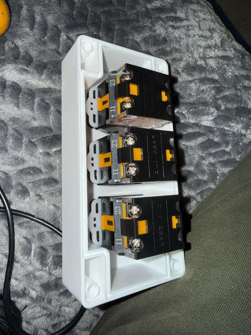
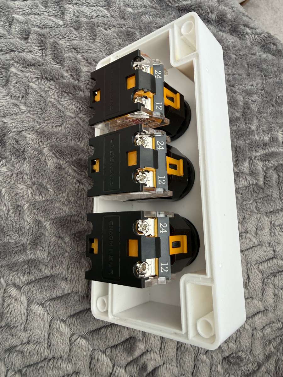
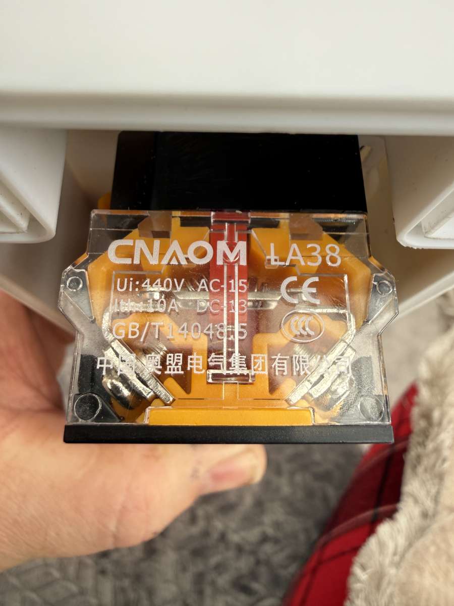
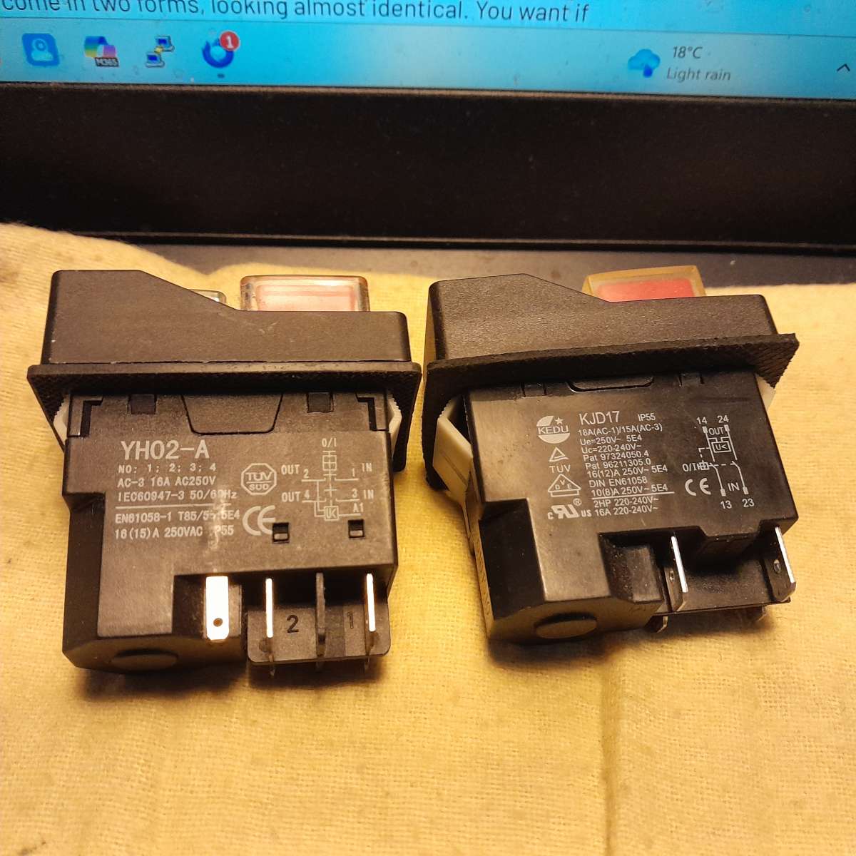
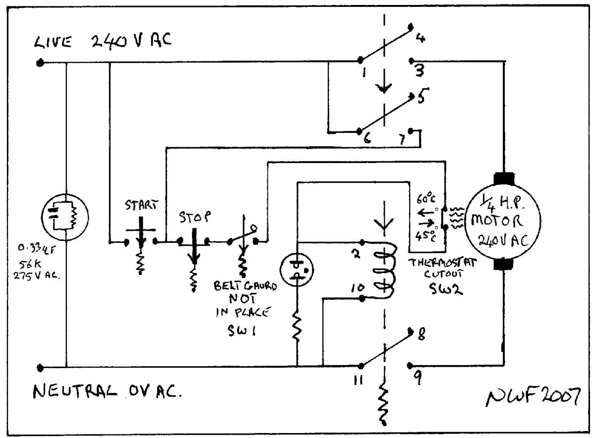
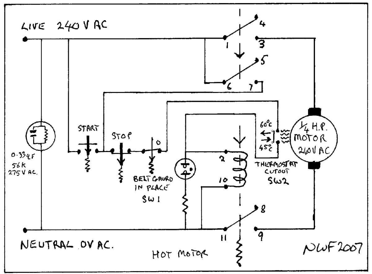
HELP!! Wiring madness
HELP!! Wiring madness
- This topic has 29 replies, 10 voices, and was last updated 10 May 2026 at 10:56 by
 Emgee.


- Please log in to reply to this topic. Registering is free and easy using the links on the menu at the top of this page.
Latest Replies
-
- Topic
- Voices
- Last Post
-
-
Lathe coolant applicators
Started by:
lucerne
in: Manual machine tools
- 12
-
6 July 2026 at 01:16
howardb
-
Accolade
Started by:
Bill Dawes
in: General Questions
- 8
-
6 July 2026 at 00:18
Nigel Graham 2
-
What Did You Do Today 2026
1
2
…
4
5
Started by:
JasonB
in: The Tea Room
- 36
-
6 July 2026 at 00:13
Nigel Graham 2
-
Unwanted Car Software Update
Started by:
Chris Crew
in: The Tea Room
- 17
-
5 July 2026 at 22:15
george baker 1
-
Laser centre finder
1
2
Started by:
Buffer
in: General Questions
- 16
-
5 July 2026 at 21:54
Vic
-
Brass covered steel
Started by:
Dougie Swan
in: General Questions
- 9
-
5 July 2026 at 20:43
Dougie Swan
-
Testing Single Point Thread Fitment
1
2
Started by:
berwick
in: Beginners questions
- 17
-
5 July 2026 at 16:44
Michael Gilligan
-
My Minnie
1
2
Started by:
Nick Welburn
in: Work In Progress and completed items
- 8
-
5 July 2026 at 15:45
Nick Welburn
-
Optimum products?
1
2
3
Started by:
Alan Ambrose
in: Manual machine tools
- 24
-
5 July 2026 at 13:22
southernchap
-
Flat Surface
1
2
3
Started by:
COLIN MARTIN 2
in: Materials
- 32
-
5 July 2026 at 13:15
southernchap
-
An arduino enigma
Started by:
duncan webster 1
in: Electronics in the Workshop
- 8
-
5 July 2026 at 10:29
John Haine
-
Easy as Pi
Started by:
Michael Gilligan
in: Clocks and Scientific Instruments
- 5
-
5 July 2026 at 10:06
michael m
-
Identifying the pitch of threading inserts
Started by:
Bill Phinn
in: Workshop Tools and Tooling
- 5
-
4 July 2026 at 20:19
Bill Phinn
-
My week this week! My workshop videos
1
2
…
12
13
Started by:
Phil Whitley
in: The Tea Room
- 16
-
4 July 2026 at 16:46
Phil Whitley
-
NPT thread
Started by:
Bill Dawes
in: General Questions
- 8
-
4 July 2026 at 15:46
Dave Halford
-
New project for 2025
1
2
Started by:
SteveP
in: I/C Engines
- 8
-
4 July 2026 at 15:12
SteveP
-
upgrade of Alibre Atom 3D
Started by:
David George 1
in: CAD – Technical drawing & design
- 6
-
3 July 2026 at 22:23
Mark Rand
-
Leadscrew Handwheel for Warco WM180
Started by:
James A
in: Manual machine tools
- 9
-
3 July 2026 at 20:45
Andy Stopford
-
Clarkson radius grinding attachment
Started by:
Andrew Tinsley
in: Workshop Tools and Tooling
- 5
-
3 July 2026 at 19:28
Clive Foster
-
Gas Tap Valves. Vintage
1
2
3
4
Started by:
dee
in: Related Hobbies including Vehicle Restoration
- 22
-
3 July 2026 at 18:36
duncan webster 1
-
Myford Ml7 Technical Drawings
1
2
3
Started by:
Harry Broadbent
in: Model Engineer & Workshop
- 28
-
3 July 2026 at 17:20
vintagengineer
-
Coventry Diehead CH Reassembly
Started by:
Tony Ray
in: Workshop Tools and Tooling
- 3
-
3 July 2026 at 10:54
bernard towers
-
24cc DIESEL ENGINE FROM SOLID
1
2
3
Started by:
dean clarke 2
in: I/C Engines
- 13
-
2 July 2026 at 22:45
dean clarke 2
-
Running 380V 3-phase motor on 230V 1-phase
1
2
3
4
Started by:
jimalm
in: Electronics in the Workshop
- 20
-
2 July 2026 at 22:38
Vic
-
Lathework for Beginners
1
2
…
4
5
Started by:
Neil Wyatt
in: Manual machine tools
- 24
-
2 July 2026 at 17:36
Howard Lewis
-
Lathe coolant applicators


