

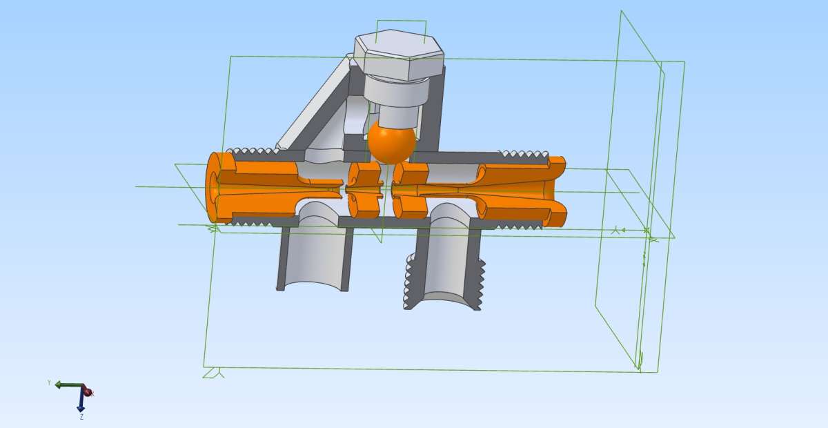
Re Inserting Angled Features – Completed The Alibre Model
Re Inserting Angled Features – Completed The Alibre Model
- This topic has 3 replies, 4 voices, and was last updated 23 October 2026 at 10:37 by
 John Hinkley.
 John Hinkley.
 Nigel Graham 2
 David Jupp
 blowlamp
 John Hinkley
- Please log in to reply to this topic. Registering is free and easy using the links on the menu at the top of this page.
Latest Replies
-
- Topic
- Voices
- Last Post
-
-
What Did You Do Today 2026
1
2
…
9
10
Started by:
JasonB
in: The Tea Room
- 55
-
23 October 2026 at 11:59
jaCK Hobson
-
What is this tool?
Started by:
jaCK Hobson
in: The Tea Room
- 6
-
23 October 2026 at 11:45
jaCK Hobson
-
Change old AC motor to BLDC motor in Sieg C6
Started by:
Jens Eirik Skogstad 1
in: Electronics in the Workshop
- 9
-
23 October 2026 at 11:22
Clive Steer
-
Re Inserting Angled Features – Completed The Alibre Model
Started by:
Nigel Graham 2
in: CAD – Technical drawing & design
- 4
-
23 October 2026 at 10:37
John Hinkley
-
Workshop Insurance.
Started by:
Andrew Tinsley
in: General Questions
- 10
-
23 October 2026 at 08:32
JohnF
-
Small (ish) horizontal mill identification “Howdle”
Started by:
Rainbows
in: Manual machine tools
- 13
-
23 October 2026 at 08:29
Dave Wootton
-
Does anyone have any info about these vices
1
2
Started by:
bjcolyer
in: Introduce Yourself – New members start here!
- 13
-
23 October 2026 at 06:38
Michael Gilligan
-
LAzar egde finder
Started by:
ian Holdsworth
in: Beginners questions
- 10
-
22 October 2026 at 23:58
Ches Green UK
-
PHP
Started by:
Michael Gilligan
in: Website Questions, Comments, and Suggestions
- 3
-
22 October 2026 at 19:36
Mark Rand
-
Stuart twin compound
Started by:
teamricky
in: Stationary engines
- 5
-
22 October 2026 at 17:56
teamricky
-
Layerling – new free CAD software for 3D printing
Started by:
Graham Stoppani
in: CAD – Technical drawing & design
- 9
-
22 October 2026 at 16:14
Fulmen
-
Close-coupled Tees (Underfloor heating)
Started by:
Andy Stopford
in: The Tea Room
- 7
-
22 October 2026 at 15:55
Macolm
-
Rivetting with a hydraulic press
1
2
Started by:
Martin Johnson 1
in: Workshop Tools and Tooling
- 19
-
22 October 2026 at 15:33
DC31k
-
ML7 change gear caluclator
Started by:
drnewcomb
in: Manual machine tools
- 8
-
21 October 2026 at 16:47
ega
-
Making a Lathe Bench for a Myford ML10
1
2
Started by:
starjump
in: Beginners questions
- 11
-
21 October 2026 at 15:33
starjump
-
Coventry Diehead CH Reassembly
Started by:
Tony Ray
in: Workshop Tools and Tooling
- 4
-
21 October 2026 at 12:46
Jan Raap
-
John Haining 2″ Ruston
Started by:
Pixel_Porpoise
in: Help and Assistance! (Offered or Wanted)
- 4
-
21 October 2026 at 11:01
Dave Halford
-
Pencil Sharpener
1
2
Started by:
Vic
in: The Tea Room
- 18
-
20 October 2026 at 23:10
Nigel Graham 2
-
Trying a new controller
Started by:
John Haine
in: CNC machines, Home builds, Conversions, ELS, automation, software, etc tools
- 4
-
20 October 2026 at 21:54
Huub
-
Model Turbines
1
2
…
26
27
Started by:
Turbine Guy
in: Stationary engines
- 28
-
20 October 2026 at 19:56
Turbine Guy
-
Model seed drill.
Started by:
colingp125halls
in: Introduce Yourself – New members start here!
- 3
-
20 October 2026 at 16:12
JasonB
-
ML10 and Chuck cleaning Information
1
2
Started by:
starjump
in: Beginners questions
- 10
-
20 October 2026 at 01:45
Grindstone Cowboy
-
carbide insert lathe tools
1
2
Started by:
davidwf
in: Workshop Tools and Tooling
- 16
-
19 October 2026 at 20:30
old mart
-
Coventry die head
Started by:
lug lord
in: Workshop Techniques
- 8
-
19 October 2026 at 18:27
John MC
-
The Latest INDEX to Model Engineer & Workshop (Also past issues of MEW)
1
2
3
Started by:
David Frith
in: Model Engineer & Workshop
- 7
-
19 October 2026 at 17:04
David Frith
-
What Did You Do Today 2026
1
2
…
9
10
 JasonB
 jaCK Hobson
 Jens Eirik Skogstad 1
 Clive Steer
 Nigel Graham 2
 Andrew Tinsley
 JohnF
 Rainbows
 Dave Wootton
 bjcolyer
 Michael Gilligan
 ian Holdsworth
 Ches Green UK
 Mark Rand
 teamricky
 Graham Stoppani
 Fulmen
 Andy Stopford
 Macolm
 Martin Johnson 1
 DC31k
 drnewcomb
 ega
 starjump
 Tony Ray
 Jan Raap
 Pixel_Porpoise
 Dave Halford
 Vic
 John Haine
 Huub
 Turbine Guy
 colingp125halls
 Grindstone Cowboy
 davidwf
 old mart
 lug lord
 John MC
 David Frith
Latest Issue
Newsletter Sign-up
Latest Replies
- What Did You Do Today 2026
- What is this tool?
- Change old AC motor to BLDC motor in Sieg C6
- Re Inserting Angled Features – Completed The Alibre Model
- Workshop Insurance.
- Small (ish) horizontal mill identification “Howdle”
- Does anyone have any info about these vices
- LAzar egde finder
- PHP
- Stuart twin compound