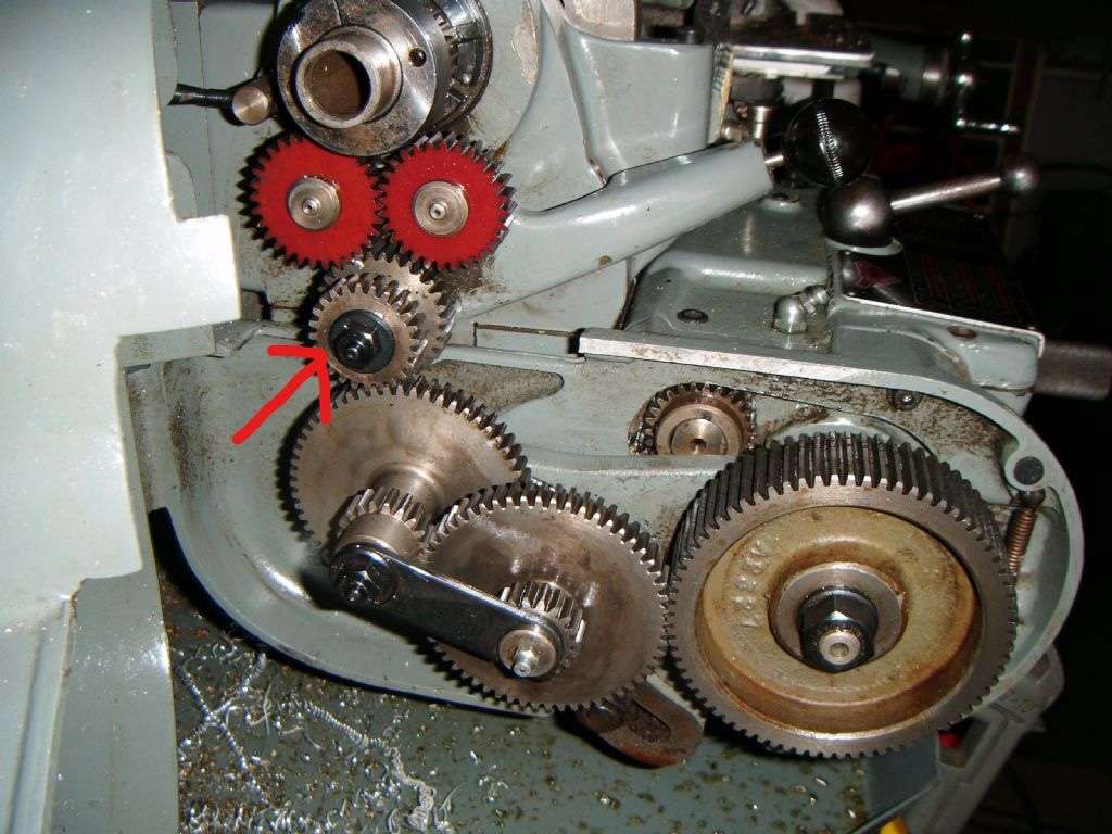
Myford ML7 gearbox and how it affects metric change wheels.

Myford ML7 gearbox and how it affects metric change wheels.

Home › Forums › Introduce Yourself – New members start here! › Myford ML7 gearbox and how it affects metric change wheels.

Viewing 12 posts - 1 through 12 (of 12 total)
  • Author
    Posts
  • #868095
    philml7
    Participant
      @philml7

      Hi,

      I have a Myford ML7 with gearbox type II. I have bought a metric set of change gears and am wanting to cut an external 8mm x 0.75 thread. I have used lathes occasionally for many years and have done some thread cutting before. I know which gear wheels to use am wondering how the gearbox affects it. Presumably, after fitting the correct gears, I need the gearbox to only have a ratio of 1:1. Is this correct and if so then how do I do that?

      Cheers,

      Phil

      #868108
      Bazyle
      Participant
        @bazyle

        see this thread/

        https://www.model-engineer.co.uk/forums/topic/metric-threads-on-a-myford-super-7-with-quick-

        change-gearbox/

        You still need to select the appropriate gearbox setting for the thread. You might also clarify what ‘metric gear set’ you actually have as there may be more than one option (I’m not a Myford user so can’t help directly)

        #868140
        Nigel Graham 2
        Participant
          @nigelgraham2

          It won’t give a 1:1 ratio but I’d start the calculations by using a simple binary ratio gearbox setting such as 16 or 32TPI, as those are half and quarter the leadscrew pitch.

          The secret seems in changing the 12 or 24T primary pinion after the reverse tumbler, so the drive ratio is altered by (12 or 24) / New.

          For example, if the gearbox could be set to 1:1 overall with a 12T pinion, to give 8tpi; the cut pitch would = 0.125″ = 3.175mm. Rather cruel to the lathe of course. Use the 24T wheel and set the gearbox to 16TPI gives the same result- a point that baffled me for a while until I studied both machine and handbook more carefully.

          So swapping that primary wheel and applying its ratio with the substitute, we now need determine what substitute tooth-count to use in place of the 24 or 12 tooth wheels, for a given gearbox setting.


          I have just spent some time trying to do that but it pushes my numeracy to the limit and I do not believe my answers. Luckily others have already done these calculations and published them!


          It’s something I would like to know too, as the Myford literature seems to advise it needs a special banjo; which of course Myford no longer stocks now that more users of these elderly lathes are using metric screws more often.

          The thread Bazyle suggests is for a Myford Super 7, and there may be important detail differences between that, your ML7 with Type II gearbox, and mine with Type 1. For a start, the gear-studs on my lathe’s banjo are on fixed centres so any other than 12 and 24T pinions may not be possible. I don’t know if the original, fully-slotted banjo could be used instead, but it would be a faff.


          I asked in a different way a couple of weeks ago, and the upshot of a lengthy thread (!) was keep the gearbox now I’ve fitted it, and use dies for the metric threads I’m ever likely to cut. Useful if most of your threads are inch-based as mine are, and the intended mm threads all small diameter; not so useful if needing screw-cut the metric ones.

          #868157
          DC31k
          Participant
            @dc31k
            On philml7 Said:

            I have a Myford ML7 with gearbox type II. I have bought a metric set of change gears

            When you state your problem in this way, you are somewhat limiting the pool of potential helpers, and the brain power at your disposal.

            Any person answering needs to know what a type II gearbox is as well the tooth count of the gears you have purchased.

            If you could write down the gear on the lathe’s mandrel, all gears in the train forming the input to the gearbox, the internal ratios of the gearbox, and the leadscrew pitch, it is at least initially a purely mathematical exercise that anyone could attempt. At this point the problem is entirely generic and not Myford-specific.

            Once you have some numbers, and only at that point, does the specific machine become important. The importance arises from the need to fit a calculated input train into the space available. That can be trial and error and also be done using cardboard discs of the correct diameter if an actual gear is not available.

            #868178
            Grindstone Cowboy
            Participant
              @grindstonecowboy

              I’ve mentioned it before, but this site https://www.ridethegeartrain.com/ is well worth a look. I don’t have a gearbox on my lathe, but I believe there are options for that in the calculations.

              Rob

              #868192
              Macolm
              Participant
                @macolm

                Perhaps to point out that the reason things are so complicated is that Imperial thread series are defined as simple ratios of threads per inch, whereas thread pitch is used for the Metric thread series. One is the reciprocal of the other.

                Thus the available thread series on an imperial box will not provide a useful series of metric threads. Different change wheels together with a suitable gearbox setting will therefore need to be chosen for each individual thread.

                #868200
                philml7
                Participant
                  @philml7

                  Thanks to all of you. I’m amazed how many replies there were in such short time!

                  I have only just changed the quadrant over to the new metric one  – and have now seen that the little chart says which gearbox levers to set, However, the new chart (which came with the metric set) suggests gears that will not fit together. There is not enough space on the quadrant!

                  Obviously it’s late now (midnight) and so I’ll continue with the problem tomorrow.

                  #868201
                  Nigel Graham 2
                  Participant
                    @nigelgraham2

                    Dc31k –

                    It’s not as arithmetically complicated as you make out; but there are serious mechanical difficulties.

                    The question is specific to Myford lathes that have 8TPI leadscrews and on the ML7s fitted with either of two patterns of Norton-type gearbox – the pattern may be important but mechanically rather than mathematically.


                    The gearbox is driven by a set of change-wheels on a banjo differing from that used for change-wheel only operation, in that the default version has fixed studs and the only adjustment is rotary about the gearbox input axis.

                    In standard trim the earlier Type 1 gearbox box uses a 24 + (flimsy)12 Teeth pair engaging the reverse tumbler, thence a reversible pair that gives threads / fine-feed choice, to a double-width gear forming the gearbox input.(I do not know if this is also true for the later Type 2 Gearbox.


                    We do not need change the wheels for inch-based threads given directly by the gearbox.

                    So we can cut those threads up to the limit set by the gearbox; 56T.P.I, I think from memory.

                    We can not cut threads not listed on the gearbox’s settings plate, save only that if you use a 24 + 24T pinion pair you need set the gearbox to indicate twice the wanted t.p.i. (Hence the two ME threads need that 12T initial pinion to reach the 32 and 40 TPI.) This gives only the advantage of a more robust driving pinion; but does double the pitch of a fine-feed. You need adjust the banjo’s angular position for this change.


                    Now we come to the difficult bit.

                    Metric and other non-inch threads.

                    The Manual for fitting and operating these gearboxes devotes two pages to Diametral and Module pitches (for worms?) and BA threads. For these you need change all those wheels on that fixed-stud banjo to ones from an assortment of odd-count wheels indeed.

                    The next page covers Metric threads, and here we need change the banjo as well, for one with studs adjustable along slots; and as with the DP, Module and BA threads set the gearbox controls to positions not TPI numbers.


                    Now, the book tabulates all the requisite intermediate change-wheels, the appropriate banjo, and the control settings, for the ML7 and ML Super 7 lathes, but it’s not easy.

                    Indeed, you may well wonder why even fit one of these gearboxes if you intend to cut many non-inch threads, because that still needs swapping gears around!

                    (For BA and smaller metric pitches, a die may be more appropriate anyway.)


                    The only way you can use one of these inch-pitch gearboxes with its own standard input banjo to cut metric threads, seems to be replace the 12+24T driving pinion with one calculated to change the entire ratio downstream of it. This is based on the fact that swapping from 12 to 24t pinions means you need select the twice-TPI count; so for mm threads the swap is to some other number.

                    These two gears are cut on a single piece of steel, so the replacement without replacing any other components would be a 12 or 24T wheel paired with the appropriate translation wheel of modest tooth count (in range 16 – 40t perhaps?), the two keyed together; and the mesh set by rotating the entire banjo.


                    I have not investigated this on my own lathe.


                    Macolm –

                    How the thread is described does not matter. You can define any thread by both turns-per-unit and pitch.

                    The difficulty is firstly, that the two systems of measurements are not compatible.

                    Secondly, the Myford lathe has an inch-based leadscrew (8TPI or 0.125″pitch) and the gearbox gives threads based only on the various inch-based series. So with its supplied input gears it can not cut BA threads (millimetric, geometrical progression), ISO pitches (millimetric, no numerical progression!) and worms (inch or mm, circular pitches).

                    You can cut a good range of standard metric threads to close accuracy on a Myford lathe using the standard change-wheels (without gearbox). The tables in the lathe manual and on a plate inside the cover, tell you which. Myford also stocks a 127T wheel to improve this selection. You might also be able to cut worms, selecting the change-wheels by pitch rather than TPI ratios.


                    So what Phil – and I and any other ML7 owner asking – need know is:

                    – can we select the primary-drive pinion between the spindle and the gearbox, to alter the entire gearbox ratio to give the wanted mm-pitch.

                    – and by using the existing banjo, which may or may not depend on which pattern of gearbox.

                    #868217
                    peak4
                    Participant
                      @peak4

                      Phil, My own Myford is a Super 7B clone, rather than an ML7, but the same principles apply.
                      Head over to my profile from my user name, and from there to my gallery.
                      There is a documents folder containing the Mk2 gearbox manual, and a pdf for fitting the metric conversion kit.
                      Just double check this is the correct manual for your gearbox, I believe the earlier one has a cover on the right hand side.

                      Don’t get confused with two other documents, one a photo of a table, and the other a spreadsheet, as they relate to a different method of metric screwcutting, substituting 33 & 34 tooth gears for the more expensive conversion kit, but this only works with the later box.

                      By the sound of it, you have the conversion kit, or at least part of it; there should be a different banjo to hold the different gears. See fig 1 in the pdf, which shows the contents of the kit.

                      You need the orange circled documents, not the blue one, which is for the alternative method avoiding the conversion kit.

                      image_2026-10-07_011943091

                      p.s. I’ve just run RideTheGearTrain  for an ML7 + Mk2 gearbox, and it does give solutions.

                      Bill

                      #868235
                      JohnF
                      Participant
                        @johnf59703

                        Phil, here are some more links to forum posts relating to the Myford Mk2 gearbox and metric threads,  you have only one gear to change and select the correct gearbox setting,  I use this method and it works well for all practical purposes.

                        You can see there are some very minor pitch errors so if you happen to need “perfect” thread pitches then you need to use the Myford metric conversion kit with a special slotted quadrant.

                        https://www.model-engineer.co.uk/forums/topic/myford-33t-and-34t-gears-for-metric-threads/

                        https://www.model-engineer.co.uk/forums/topic/myford-metric-lathe-leadscrew/

                        https://www.model-engineer.co.uk/forums/topic/availability-of-a-t33-t34-myford-change-gears/page/2/

                        Phot from another post showing the only gear you need to change when using the table in the move posts or in peak4’s post — hope this helps John

                        88C13158-8EDE-4844-980E-A9610AC6DAF7


                        #868279
                        philml7
                        Participant
                          @philml7

                          Gosh, what a cornucopia of info you guys are!! Thanks so much everyone and I will digest it and follow the links given. I was trying to avoid buying a die, seeing as I may only use it once.

                          I bought the ML7 from my workplace, when they were reorganising  their workshop. It’s in good condition, but I’m used to using larger more modern lathes. The 8mm x 0.75 thread is for reconditioning/improving an old Boxford/Myford tool post grinder. Both motor and chuck needed replacement.


                          #868290
                          Nigel Graham 2
                          Participant
                            @nigelgraham2

                            Peak4, JohnF –

                            Thankyou very much.

                            I’ll have a look on my ML7.

                            Myford’s own manual for the gearbox does not even mention this possibility!

                          Viewing 12 posts - 1 through 12 (of 12 total)
                          • Please log in to reply to this topic. Registering is free and easy using the links on the menu at the top of this page.

                          Latest Replies

                          Viewing 25 topics - 1 through 25 (of 25 total)
                          Viewing 25 topics - 1 through 25 (of 25 total)

                          View full reply list.