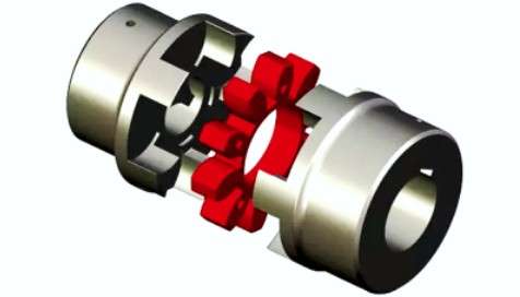
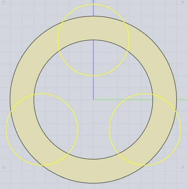
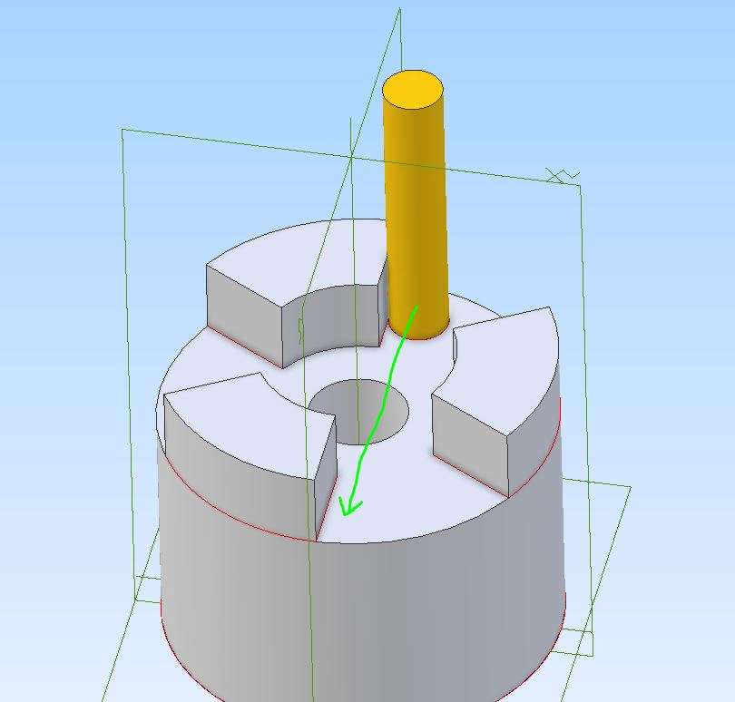
Reworking a Spider/jaw coupling
Reworking a Spider/jaw coupling
- This topic has 43 replies, 11 voices, and was last updated 27 May 2026 at 06:42 by
 Paul McDonough.
- Please log in to reply to this topic. Registering is free and easy using the links on the menu at the top of this page.
Latest Replies
-
- Topic
- Voices
- Last Post
-
-
Axle pin question – choice of material and possible need for case hardening?
Started by:
barryblundell
in: Materials
- 5
-
17 June 2026 at 01:19
howardb
-
Linear encoders
Started by:
Speedy Builder5
in: Electronics in the Workshop
- 8
-
17 June 2026 at 01:07
Nigel Graham 2
-
Green Dragon Sustainable Fuel
Started by:
Neil Wyatt
in: Locomotives
- 9
-
16 June 2026 at 23:17
howardb
-
ML7 – Zeroing the Topslide?
1
2
Started by:
Dr_GMJN
in: Workshop Techniques
- 21
-
16 June 2026 at 22:18
ega
-
Orbital – Not your Usual Oscillator!
Started by:
JasonB
in: Stationary engines
- 11
-
16 June 2026 at 21:38
Andrew Crow
-
AJ Reeves 5 inch driving trolley bogies
Started by:
Ian R
in: Locomotives
- 3
-
16 June 2026 at 21:28
paul rushmer
-
How Good Are 3D Printers?
1
2
Started by:
Neil Wyatt
in: 3D Printers and 3D Printing
- 14
-
16 June 2026 at 20:56
Mark Rand
-
upgrade of Alibre Atom 3D
Started by:
David George 1
in: CAD – Technical drawing & design
- 4
-
16 June 2026 at 19:31
David Jupp
-
Greetings
Started by:
dee
in: Introduce Yourself – New members start here!
- 1
-
16 June 2026 at 16:53
dee
-
Warco DNC18 Mill/Digital Dream controllers
Started by:
Pippin
in: CNC machines, Home builds, Conversions, ELS, automation, software, etc tools
- 9
-
16 June 2026 at 15:44
Derek cottiss
-
My adventures with a bench top CNC mill
1
2
3
Started by:
John Hinkley
in: CNC machines, Home builds, Conversions, ELS, automation, software, etc tools
- 8
-
16 June 2026 at 12:10
John Hinkley
-
Steam Engine
Started by:
steven49
in: Introduce Yourself – New members start here!
- 1
-
16 June 2026 at 09:35
steven49
-
Lathe cutting aggressive taper
Started by:
Lee Kennedy
in: Manual machine tools
- 11
-
16 June 2026 at 08:09
Nicholas Farr
-
KMO RETROL 1/4 Scale Lister D Engine with some Mods.
Started by:
Blue Heeler
in: I/C Engines
- 2
-
16 June 2026 at 04:46
Blue Heeler
-
Wallace valvegear simulator
Started by:
Kevan Shaw
in: General Questions
- 7
-
15 June 2026 at 19:29
John Purdy
-
Replacement Allbrit Draftmaster Protractor Rulers
Started by:
wigan2026
in: Workshop Tools and Tooling
- 7
-
15 June 2026 at 18:06
Grindstone Cowboy
-
Commercial ads in classified
Started by:
Andrew Tinsley
in: General Questions
- 2
-
15 June 2026 at 15:48
JasonB
-
Super Simplex Build
Started by:
Peter Hoerlein
in: Work In Progress and completed items
- 7
-
15 June 2026 at 07:08
Peter Hoerlein
-
Running 380V 3-phase motor on 230V 1-phase
Started by:
jimalm
in: Electronics in the Workshop
- 13
-
14 June 2026 at 21:24
Julie Ann
-
Taper Identification
Started by:
Andrew Tinsley
in: Workshop Tools and Tooling
- 2
-
14 June 2026 at 20:46
Chris Crew
-
Lightning
1
2
3
Started by:
duncan webster 1
in: Electronics in the Workshop
- 14
-
14 June 2026 at 11:07
Robert Atkinson 2
-
Testing Single Point Thread Fitment
Started by:
berwick
in: Beginners questions
- 12
-
14 June 2026 at 10:18
alecs
-
Taylor Hobson Pantograph Engraver Model D
1
2
Started by:
jaCK Hobson
in: Workshop Tools and Tooling
- 8
-
13 June 2026 at 17:56
jaCK Hobson
-
What Did You Do Today 2026
1
2
…
4
5
Started by:
JasonB
in: The Tea Room
- 34
-
13 June 2026 at 15:38
Dalboy
-
Hindu ascetic in picture gallery
Started by:
Bill Phinn
in: Website Questions, Comments, and Suggestions
- 3
-
13 June 2026 at 15:37
Neil Wyatt
-
Axle pin question – choice of material and possible need for case hardening?
Latest Issue

Newsletter Sign-up
Latest Replies
- Axle pin question – choice of material and possible need for case hardening?
- Linear encoders
- Green Dragon Sustainable Fuel
- ML7 – Zeroing the Topslide?
- Orbital – Not your Usual Oscillator!
- AJ Reeves 5 inch driving trolley bogies
- How Good Are 3D Printers?
- upgrade of Alibre Atom 3D
- Greetings
- Warco DNC18 Mill/Digital Dream controllers

