Any spot welder experts about?

Any spot welder experts about?

Home Forums General Questions Any spot welder experts about?

Viewing 18 posts - 1 through 18 (of 18 total)
  • Author
    Posts
  • #216377
    frank brown
    Participant
      @frankbrown22225

      I got an old spot welding transformer from a mate decades ago and decided to use now. The reason was to connect to stainless steel tabs on rechargeable ni-cad batteries in order to re-use them.

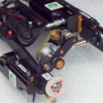
      The transformer is about 7" square and 9" long with the output being a couple of 1/2" copper bars about 15" long.It is all painted light green. The mains connection are on a paxolin panel. four terminals, "C" which I took for common (neutral), then .16 ohms to "H", or .255 ohms to "M", or .265 ohms to "L" .

      Using the C to L connections , I got 3.5V out and enough current to heat red hot and remove a fair section of a .005" X .25" stainless steel tab.. Despite this I think i might have a good joint.

      So C to L , highest primary resistance, highest number of turns, so lowest output voltage. But still an excessive current. Anny suggestions for reducing the output current?

      As the kit did not blow the 13A mains fuse during my brief experiment, I presume the transformer has got a bit of leakage inductance built it to limit the current.

      All suggestions welcome.

      Frank

      #24271
      frank brown
      Participant
        @frankbrown22225
        #216392
        Mike Poole
        Participant
          @mikepoole82104

          Introducing more resistance into the secondary circuit will limit the current but will generate heat, in the car industry water cooling is used to keep things from self destruction and stop the resistance rising which will affect weld quality. From the 70's to 90's control of the primary was effected with SCR control but with ignitrons before that. The firing angle of each half cycle could be delayed to control the primary current and thus the secondary current. The secondary circuit of a weld gun is constructed from aluminium and copper to minimise losses, if you put a big bar of steel in your circuit it might limit your current enough.

          Mike

          #216624
          peter walton 1
          Participant
            @peterwalton1

            The tabs on NiCad batteries are spot welded using a capacitive discharge welder.

            Do a search on google!

            Plenty of info for self build

            peter

            #216751
            frank brown
            Participant
              @frankbrown22225

              I have tried that.. The problem is that I have a transformer which is a proper spot welding transformer which could be rated as high as 5 kW, not a 800W micro wave transformer with a home wound secondary. Also they have no way of controlling the current, as they don't have that much to start with.

              Have you any figures for the Coulomb rating of the capacitor type ( 1/2 C V^2)?

              Frank

              #216768
              Mike Lightfoot
              Participant
                @mikelightfoot72419

                Good evening, I have somewhere a drawing and the spec for a tab welder if anyone is interested I will try and dig it out might take a day or so let me know ( it is as suggested a capacitive discharge welder)

                #216770
                ASF
                Participant
                  @asf

                  I have made a few new battery packs up and it rejuvenated the power tools no end!

                  I did try to reuse the tabs, but found that,because new batteries were more powerful, it caused the old tabs to heat up.

                  So to fix this issue, I used copper pipe cut down the length, flattened then cut into little strips. Polished them up and soldered the tabs with a 100 watt iron.

                  The soldering is simple. The hard part is keeping all the batteries in the shape of the plastic pack.

                  #216912
                  frank brown
                  Participant
                    @frankbrown22225

                    yes I have done that in the past too. I think the solderable tabs are nickel plated steel, which will solder with difficulty, they (or at least my ones are a bit thicker .007"?). But with the stainless tabs I have had no luck at all, hence my feeble attempts at getting a spot welder to work. So far no series resistor in primary is too much current, 100 ohms too much resistance.

                    Today I spent wrestling with the transformer and its 1/2" output bus bars and building a cover over the fire element resistor which is now 50 ohms and is still too high.

                    I found a number on the transformer :- BTX 7235A 55 P1 Ring any bells

                    Frank

                    #216917
                    ASF
                    Participant
                      @asf

                      well i also found that stainless was hard to solder. That is why i used copper pipe. I ripped the lightweight tabs off, rubbed the battery on some emery and they soldered easy.

                      cant help with the way you are trying to do it though

                      #216924
                      Ian P
                      Participant
                        @ianp
                        Posted by frank brown on 18/12/2015 20:08:47:

                        yes I have done that in the past too. I think the solderable tabs are nickel plated steel, which will solder with difficulty, they (or at least my ones are a bit thicker .007"?). But with the stainless tabs I have had no luck at all, hence my feeble attempts at getting a spot welder to work. So far no series resistor in primary is too much current, 100 ohms too much resistance.

                        Today I spent wrestling with the transformer and its 1/2" output bus bars and building a cover over the fire element resistor which is now 50 ohms and is still too high.

                        I found a number on the transformer :- BTX 7235A 55 P1 Ring any bells

                        Frank

                        Frank

                        I cannot claim to be an expert on spot welding but I think putting resistance in the output of the transformer is the wrong approach. Resistance welding (which I think is the correct terminology) looks very simple but there are a lot of factors that affect the weld quality. (type of material, electrode mechanical pressure, length of current pulse etc)

                        All the spot welders I have come across have a control circuit on the primary side, mostly its some sort of timer and the current is fixed at maximum by the design. If your welder was capable of 1000 Amps it could still weld very thin steel shim as long as the current pulse was very short, but mechanical relays and timers would not be precise enough to give repeatable pulses for thin material. I have used 'SSR' (Solid State Relay) modules in conjunction with a 555 timer IC to vary the weld time (switches the primary side of the transformer) but whilst I can weld 0.5mm SS sheet I doubt it would give consistent results on thin battery tabs. If your transformer is the type used for car bodywork repairing (mine was) it is out of proportion for what you want to do.

                        It might be worth experimenting though with resistance on the primary side of the transformer, 100W lightbulb or a fan heater element for example.

                        Ian P

                        #216925
                        Ian P
                        Participant
                          @ianp
                          Posted by frank brown on 18/12/2015 20:08:47:

                          yes I have done that in the past too. I think the solderable tabs are nickel plated steel, which will solder with difficulty, they (or at least my ones are a bit thicker .007"?). But with the stainless tabs I have had no luck at all, hence my feeble attempts at getting a spot welder to work. So far no series resistor in primary is too much current, 100 ohms too much resistance.

                          Today I spent wrestling with the transformer and its 1/2" output bus bars and building a cover over the fire element resistor which is now 50 ohms and is still too high.

                          I found a number on the transformer :- BTX 7235A 55 P1 Ring any bells

                          Frank

                          Frank

                          I cannot claim to be an expert on spot welding but I think putting resistance in the output of the transformer is the wrong approach. Resistance welding (which I think is the correct terminology) looks very simple but there are a lot of factors that affect the weld quality. (type of material, electrode mechanical pressure, length of current pulse etc)

                          All the spot welders I have come across have a control circuit on the primary side, mostly its some sort of timer and the current is fixed at maximum by the design. If your welder was capable of 1000 Amps it could still weld very thin steel shim as long as the current pulse was very short, but mechanical relays and timers would not be precise enough to give repeatable pulses for thin material. I have used 'SSR' (Solid State Relay) modules in conjunction with a 555 timer IC to vary the weld time (switches the primary side of the transformer) but whilst I can weld 0.5mm SS sheet I doubt it would give consistent results on thin battery tabs. If your transformer is the type used for car bodywork repairing (mine was) it is out of proportion for what you want to do.

                          It might be worth experimenting though with resistance on the primary side of the transformer, 100W lightbulb or a fan heater element for example.

                          Ian P

                          #216926
                          Neil Wyatt
                          Moderator
                            @neilwyatt

                            You probably need a MUCH smaller resistor.

                            You could try experimenting with an old-style electric fire bar with a big croc clip as a rheostat ((I love that word).

                            #216931
                            Ian P
                            Participant
                              @ianp
                              Posted by Neil Wyatt on 18/12/2015 20:49:48:

                              You probably need a MUCH smaller resistor.

                              You could try experimenting with an old-style electric fire bar with a big croc clip as a rheostat ((I love that word).

                              It needs to be small in Ohmic value but capable of passing a very high current.

                              Think about the cross sectional area of the heater element wire in relation to the battery tab (let alone the copper bar the secondary 'winding' is made of, the element wire will be a good fuse!

                              Ian P

                              #216954
                              John Haine
                              Participant
                                @johnhaine32865

                                The ideal approach would be a variac to adjust the voltage driving the primary. A thyristor speed control might also do the job. A resistor in the secondary would have to be rather low and hard to control.

                                #216991
                                Neil Wyatt
                                Moderator
                                  @neilwyatt
                                  Posted by Ian Phillips on 18/12/2015 21:07:26:

                                  Posted by Neil Wyatt on 18/12/2015 20:49:48:

                                  You probably need a MUCH smaller resistor.

                                  You could try experimenting with an old-style electric fire bar with a big croc clip as a rheostat ((I love that word).

                                  It needs to be small in Ohmic value but capable of passing a very high current.

                                  Think about the cross sectional area of the heater element wire in relation to the battery tab (let alone the copper bar the secondary 'winding' is made of, the element wire will be a good fuse!

                                  Ian P

                                  Indeed, but the heater will cope with a massive overload for a second or so, unlike a fuse it is designed to run red hot for hours on end. It's worth a try, and you can always use multiple strands of the wire (I used three to make a shunt for an ammeter once).

                                  Edited By Neil Wyatt on 19/12/2015 09:35:33

                                  #216995
                                  Ian S C
                                  Participant
                                    @iansc

                                    There is a thread on Google; I was looking through a number of sites for ideas on making a spot welder from a Micro wave oven transformer, there was one with the two electrodes parallel for welding tabs on, it mentioned a resistor, fairly low value, high wattage.

                                    Ian S C

                                    #216996
                                    Neil Wyatt
                                    Moderator
                                      @neilwyatt

                                      This is a nice simple design,

                                      http://www.philpem.me.uk/elec/welder/

                                      http://www.philpem.me.uk/elec/welder/images/schematic.png

                                      You need about 0.6 farads of capacitance, apparently 'I've heard from a few people who have managed to build welders based on the one-farad car-audio capacitors, after removing the blinking-lights display circuitry from the top of them.'

                                      Also useful safety advice.

                                      Neil

                                      #216998
                                      Clive Hartland
                                      Participant
                                        @clivehartland94829

                                        I have never had any trouble soldering tabs to Ni cads, Using a solder with a flux core. Pre-solder the joint and then apply heat to do the joint. Part of my work was re-celling Ni cad battery packs, sometimes 10 a day , charging and discharging before going back to customer. As said the joint surfaces were cleaned with emery and quickly tinned.

                                        If you are really having trouble buy some flux for stainless steel but beware as it extremely dangerous and do not get it on your bare skin nor breathe the fumes.

                                        Clive

                                      Viewing 18 posts - 1 through 18 (of 18 total)
                                      • Please log in to reply to this topic. Registering is free and easy using the links on the menu at the top of this page.

                                      Latest Replies

                                      Home Forums General Questions Topics

                                      Viewing 25 topics - 1 through 25 (of 25 total)
                                      Viewing 25 topics - 1 through 25 (of 25 total)

                                      View full reply list.