Centralising work on ‘stepper driven’ rotary table?

Centralising work on ‘stepper driven’ rotary table?

Home Forums General Questions Centralising work on ‘stepper driven’ rotary table?

Viewing 25 posts - 1 through 25 (of 27 total)
  • Author
    Posts
  • #191858
    Ian P
    Participant
      @ianp

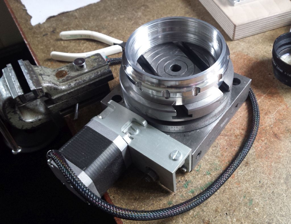
      I have a small (100mm) rotary table to which I added a stepper motor and a Steve Ward controller. It works really well but now I have come to use it in earnest for the first time I find it most impractical!

      The only way I can rotate the table is with the stepper drive, so even on the fastest speed is pretty slow. If I could spin the table by hand I could quickly centre the work with a DTI. This workpiece is pretty unsuitable to use any sort of centralising jig as its like a short slice of a large tube. As the OD is nearly as big as the table I am going to put the work clamps on the inside because its the OD of the job that I want to machine.

      I cannot be the first person to see this problem, how do other people use a DTI on something that hardly rotates?

      Ian P

      #23916
      Ian P
      Participant
        @ianp
        #191861
        JasonB
        Moderator
          @jasonb

          Coax indicator would work on that size tube, ctr table below spindle, mount work loosly and adjust until the coax shows true.

          If you don't have a coax just mount the dti on a suitable bar in the spindle and rotate that, bit of a pain looking at the back of it but will get the job done.

          Edited By JasonB on 31/05/2015 17:39:25

          #191865
          Les Jones 1
          Participant
            @lesjones1

            Hi Ian,
            Doest the rotary table not have a lever to disengage the worm from the wheel ?

            Les.

            #191891
            Ian P
            Participant
              @ianp

              Jason

              I must admit I had not thought of that method although it does double the amount of work and setting up time and I suppose adds a potential source of error.

              Not having a coaxial indicator I manage with one DTI so its a slow process anyway which usually involves me banging my head against some sharp object to get a back view of the indicator.

              Les

              The rotary table is a very simple affair, an eBay purchase which I think originated from RDG. The worm is permanently engaged and the mesh adjustment device only has a very limited range so does move free of the pinion.

              I think I will abandon this RT for this job. I have a home made rotating table (10" diameter aluminium plate mounted on a car hub with integral bearings) which I can index to the 12 positions so I can mill finger notches on the ring.

              Ian P

              #191911
              Muzzer
              Participant
                @muzzer

                Doesn't sound as if you have a DRO but that would be an ideal solution. You can set the RT centre using an edge finder on the centre hole (it's often an MT taper) and store the position. Then once you have set up the work, you can recall the position quickly and easily. Couldn't manage without a DRO now….

                #191913
                Bowber
                Participant
                  @bowber

                  My rotary table has the adjustment and when you take it to it's slackest it runs free, then when I've centred the job I take the slack up.

                  Steve

                  #191914
                  Ian P
                  Participant
                    @ianp
                    Posted by Muzzer on 31/05/2015 21:23:30:

                    Doesn't sound as if you have a DRO but that would be an ideal solution. You can set the RT centre using an edge finder on the centre hole (it's often an MT taper) and store the position. Then once you have set up the work, you can recall the position quickly and easily. Couldn't manage without a DRO now….

                    I do have a DRO on the mill but I don't see how it helps set up work on the RT.

                    Maybe a clue in your remark, 'once you have set up the work'!

                    #191917
                    Anonymous
                      Posted by Ian Phillips on 31/05/2015 21:27:18:

                      Posted by Muzzer on 31/05/2015 21:23:30:

                      Doesn't sound as if you have a DRO but that would be an ideal solution. You can set the RT centre using an edge finder on the centre hole (it's often an MT taper) and store the position.

                      I do have a DRO on the mill but I don't see how it helps set up work on the RT.

                      Roughly centre the edge finder over the RT central hole by eye. Zero it on one side of the central hole, go to the other side using X or Y slide only and pick up the opposite edge. Use the ½ function on the DRO to give the middle. Do the same on the other axis with the original axis set on zero. Then move to each of the four cardinal points as a sanity check, and possibly fine tuning. In effect it is a means of implementing Osborne's manoeuvre.

                      Andrew

                      #191920
                      Ian P
                      Participant
                        @ianp

                        Andrew

                        Does Osborne's manoeuvre follow the same rules as those used in Mornington Crescent?

                        Seriously though, the DRO method you describe is great for getting the RT in the right place but it does nothing for mounting the job on the RT (when you cannot rotate the table easily)

                        Ian P

                        #191929
                        Bowber
                        Participant
                          @bowber

                          Sorry, should have read your reply properly, you do have adjustment but not enough to run freely.
                          It's a pain but I used to just run mine round with the stepper slowly, it still only took a few minutes to set up the job it just feels frustrating watching it turn slowly round.

                          Steve

                          #191931
                          Anonymous

                            No, it's a real technique not an improvisation. wink 2

                            I recall setting up something similar on the RT, although for the life of me I can't remember what it was. I zero'd the DRO over then centre of the RT as described. I knew the OD of the part and of the table, so I could set it roughly central with a ruler. Then with a length of silver steel of known diameter in a drill chuck I can touch off on the four cardinal points on the work, ID or OD, and nudge the work until all four readings are the same.

                            Andrew

                            #191934
                            Enough!
                            Participant
                              @enough
                              Posted by Ian Phillips on 31/05/2015 17:24:46:

                              The only way I can rotate the table is with the stepper drive,

                              Which suggests that your stepper has a single ended shaft. If you can fit a double ended version instead, you can attach a knob/handle to the other end and rotate the table manually.

                              #191976
                              Muzzer
                              Participant
                                @muzzer

                                Like many DROs, mine has an absolute datum and a temporary datum. I would set up the absolute datum at the centre of the RT as Andrew suggests, then switch to temporary datum to pick up the actual position of the workpiece. By switching between the 2 datums (data?), you can compare the centres of the work and the RT and gradually reduce the difference to the required level. Depending what the shape of the work is, you may not need to rotate the RT at all, eg if it's got a circular or other regular feature on the top face. The other benefit of this approach is that you can move the table around but still return the centre of the RT to the correct position afterwards.

                                I know what you mean about rotating the RT. In my case, when I was using the table for indexing, I used my cordless drill / driver to spin between positions. The hex socket bolt on the end of the shaft allowed me to use a hex driver bit. The only downside was that it could only be driven in one direction or the bolt and handwheel would come undone. Some form of driving feature (a pinned or keyed hex head?) would get around that. Presumably, by fitting the stepper, you have removed this option.

                                Murray

                                #191980
                                Michael Gilligan
                                Participant
                                  @michaelgilligan61133
                                  Posted by Ian Phillips on 31/05/2015 17:24:46:

                                  I have a small (100mm) rotary table to which I added a stepper motor and a Steve Ward controller. It works really well but now I have come to use it in earnest for the first time I find it most impractical!

                                  The only way I can rotate the table is with the stepper drive, so even on the fastest speed is pretty slow. If I could spin the table by hand I could quickly centre the work with a DTI. This workpiece is pretty unsuitable to use any sort of centralising jig as its like a short slice of a large tube. As the OD is nearly as big as the table I am going to put the work clamps on the inside because its the OD of the job that I want to machine.

                                  I cannot be the first person to see this problem, how do other people use a DTI on something that hardly rotates?

                                  Ian P

                                  .

                                  Ian,

                                  Forgive me if I'm missing something [such as the stepper torque being too low], but; isn't that exactly what Jog Mode is intended for ?

                                  MichaelG.

                                  #191987
                                  Vic
                                  Participant
                                    @vic

                                    Someone on here, or perhaps another forum said he just so puts a plain centre in the quill of his mill and brings it down onto the bore of the RT to centre it. Would this not work for you?

                                    #191988
                                    Martin Kyte
                                    Participant
                                      @martinkyte99762

                                      Put a female centre in the R Table and a male in the Mill quill. Bring the two together and clamp the RT down. The centre of the RT is now co-axial with the quill. Fix your dial gauge in the quill OFF-CENTRE so that when the quill is rotated the DTI swings at the radius of the workpiece. Centre the work by rotating the quill (by hand). No need to rotate the table at all.

                                      regards Martin

                                      #191989
                                      JasonB
                                      Moderator
                                        @jasonb
                                        Posted by Vic on 01/06/2015 14:24:52:

                                        Someone on here, or perhaps another forum said he just so puts a plain centre in the quill of his mill and brings it down onto the bore of the RT to centre it. Would this not work for you?

                                        "This workpiece is pretty unsuitable to use any sort of centralising jig as its like a short slice of a large tube. As the OD is nearly as big as the table"

                                        #191997
                                        Vic
                                        Participant
                                          @vic

                                          Ah, thanks Jason, I missed that.

                                          In that case this is a good excuse to make a rotary Laser Centre Finder. Still making mine but have a look here about 2 mins in.

                                          #191999
                                          Ed Duffner
                                          Participant
                                            @edduffner79357

                                            Hi Ian,

                                            Could you machine a cap plate with a shoulder to sit in the top of the ring and clamp it through the centre, down through the RT, or even 4 bolts if it's the same RT as in your album, using the T-slots. The cap could have an edge which could then be clocked. Centre the RT first, then centre the piece using the cap edge as the register?

                                            Ed.

                                            Edited By Ed Duffner on 01/06/2015 16:49:38

                                            #192003
                                            Ian P
                                            Participant
                                              @ianp

                                              Thanks for all the suggestions. I had not explored Michael G's suggestion about the jog function which as he says would make the task more easily doable.

                                              I suppose I am getting lazy and always looking for shortcuts but thought I should use the RT now I've finished it. I have done quite a bit of work that by rights would have been a lot easier on a conventional rotary table (with or without stepper) but which I did with a free turning turntable that I use with jury rigged stops and index holes.

                                              On this particular part I just wanted to create a series of finger grip notches so great accuracy is not really required. However as I cut them with radius end cutter I thought that any eccentricity might show up. I used my manual turntable this time but I have taken a picture of the stepper driven table with the job sat on it to show why I posed the question.

                                              The ring has two internal threads M75x1.5 and M75x2 Neither is very accurately concentric with the part OD (Just where the 3 jaw puts them) The OD was finished last, again held on the threaded ID by the 3 jaw.

                                              Obviously I could not clamp the part down on its outer edge so I intended to use the T slots in the central void and true up using a DTI on the OD. On my manual table I would have mounted and trued the job in 5 minutes (to 0.005mm) mainly because the table is so free turning.

                                              If there was more than one to make I could fasten a disk of ali scrap to the small table using two bolts and milled a circular recess for the part to drop into. Two more bolts through holes in the plate would fix the job down. Anyway thats for next time.

                                              Ian P

                                              95mm rotary table.jpg

                                              #192017
                                              Vic
                                              Participant
                                                @vic

                                                This is what you get with a Rotary Laser. Alter the angle/height of the unit to fit the work to align it.

                                                #192025
                                                Ian P
                                                Participant
                                                  @ianp
                                                  Posted by Vic on 01/06/2015 19:38:37:

                                                  This is what you get with a Rotary Laser. Alter the angle/height of the unit to fit the work to align it.

                                                  That looks fantastically better than I expected after looking at the spot of light given by the laser modules I have seen, is your a home made device?

                                                  Ian P

                                                  #192029
                                                  Vic
                                                  Participant
                                                    @vic

                                                    Yes, I'm still working on it but it's nearly there.

                                                    #198648
                                                    Stephen Ward 1
                                                    Participant
                                                      @stephenward1

                                                      Bit late to this but….

                                                      I left the eccentric in place on my table so I can quickly disengage the motor and spin the table by hand – can't you do this?

                                                    Viewing 25 posts - 1 through 25 (of 27 total)
                                                    • Please log in to reply to this topic. Registering is free and easy using the links on the menu at the top of this page.

                                                    Latest Replies

                                                    Home Forums General Questions Topics

                                                    Viewing 25 topics - 1 through 25 (of 25 total)
                                                    Viewing 25 topics - 1 through 25 (of 25 total)

                                                    View full reply list.