My Faircut Lathe

Advert

My Faircut Lathe

Home Forums Manual machine tools My Faircut Lathe

Viewing 25 posts - 26 through 50 (of 90 total)
  • Author
    Posts
  • #426431
    Andy Carlson
    Participant
      @andycarlson18141

      A bit of a digression from getting the lathe installed and running… my thoughts are also turning to tooling. The lathe came with some very useful items but there are a few obvious gaps.

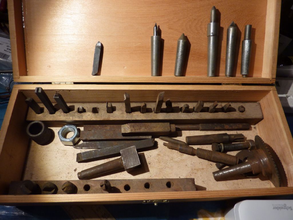
      The smaller bits of tooling came in a nice wooden box. Some have had a bath in citric acid to get the rust off but there are plenty more to do.

      p1060949.jpg

      I'm guessing the black tools are carbon steel?

      How to hold 1/4 inch or so tools in the old school tool holder on the lathe is another question to resolve.

      There were some drills and centre drills loosely mounted in morse taper arbors. This puzzles me… how would they stay put when used?

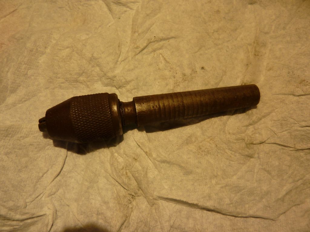
      This was the only drill chuck…

      p1060948.jpg

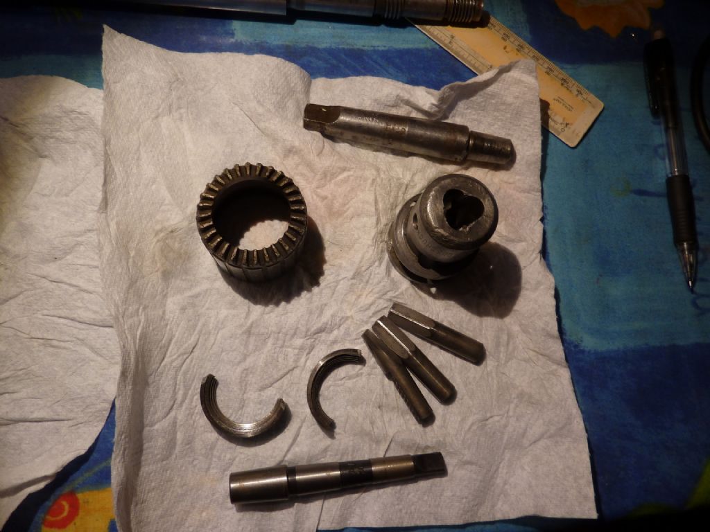
      It may find a use but it's not the best so my thoughts turned to a box full of rusty tools that we found when clearing out my late father in law's garage. It probably belonged to his father. In there was a Jacobs No 32 chuck on an MT2 arbor. It has clearly seen a lot of action but the jaws don't look too bad. I managed to persuade it off the arbor (someone else had already drilled through the body) and have sourced an MT1 arbor, so hopefully this will be more suitable

      p1060947.jpg

      Advert
      #426495
      Perko7
      Participant
        @perko7

        Just came across this thread, saw the photos of the motor arrangement, its a bit like the arrangement on my Ideal lathe except that I assembled the motor and layshaft into a sub-unit that hinged at the bottom and used the weight of the motor and layshaft to tension the flat belt. Works pretty well with enough 'grip' for decent depth of cut and feed rate without overstressing an old machine, but if I get too ambitious (or something goes wrong) the belt just slips.lathe set up 001-rc.jpg

        #426527
        Andy Carlson
        Participant
          @andycarlson18141

          I like your countershaft pedastals – very 'in keeping' with the lathe. My setup at the moment is just a small change from the previous owner's setup (using the same parts) which lacked any means of adjusting the flat belt tension and the vee belt can only be adjusted by moving the plumber block bearings up or down the slots in the angle iron. 'In keeping' it aint!

          The previous owner never really used the lathe so I expect that my setup will prove unsatisfactory in real use but at the moment I want the lathe up and running and will worry about making a better setup later on. It has at least managed an easy test cut with the belt tensioned just by friction with the not inconsiderable weight of the motor and lathe keeping things in place.

          I completely agree that slipping belts are a good thing – it's good to have some sort of 'safety valve' because things DO go wrong.

          #426548
          Andy Carlson
          Participant
            @andycarlson18141

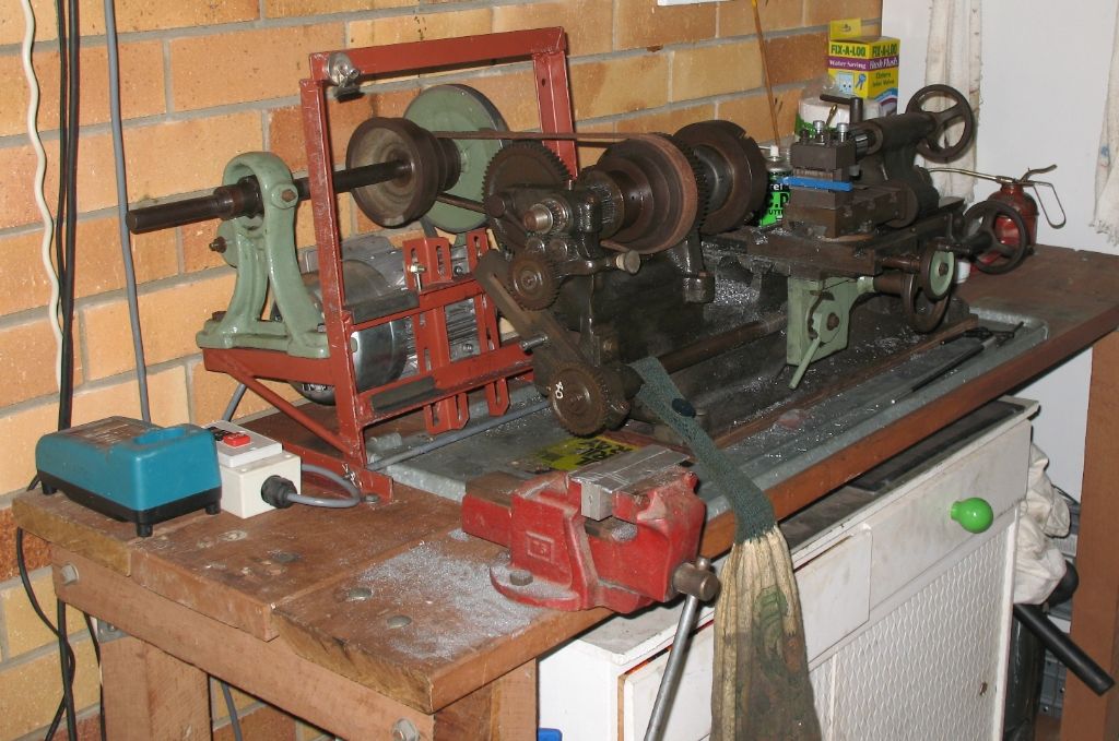
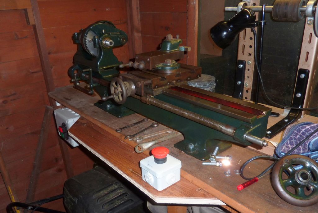
            A little progress update on the installation. Over the bank holiday I got the bench braced, the lathe bolted down and some electrics installed. Plenty more to do yet, hence the absence of the motor and tailstock from the photo.

            p1060955.jpg

            #428536
            Andy Carlson
            Participant
              @andycarlson18141

              Another update on the Faircut…

              On the face of it there is not much to show for several weeks of effort since I started this thread but hopefully the machine is now in a better state and ready for some real work.

              The biggest job has been improving the insulation on the 90 year old Century Electric motor. The drive has been rearranged to move the motor further towards the headstock end but it's still not out of range of swarf. I've added a plastic cover to keep swarf out of the many holes in the ornate end casing of the motor. It's not pretty, being a cut down horse feed additives bucket but it does the job for now. Likewise my oiler covers are tin foil… definitely another job for the 'to do' list.

              Most but not all of the bits have been off the lathe. The headstock has been dismantled and some minor galling on the spindle cleaned up. Surprisingly the spindle bearing bolts were just finger tight. I have snugged these down but they are probably still on the loose side because there is always the worry of going too far and breaking the casting. I've seen some suggestions to put shims in the gap. To the best of my knowledge this is not the right thing to do when the bearing housing is only split on one side but it would be good to know if my knowledge is correct here.

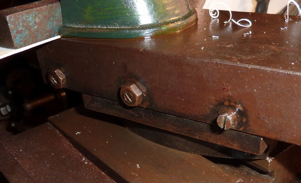
              All of the gibs were quite sloppy so all of the screws have been out, freed of crud and refitted. Actually, all bar one… One of the screws on the compound slide is different from the others and won't budge. My guess is that its threads are cut a bit shallow. I've tried WD40 and clamping the head in an ER16 collet to get plenty of torque on it but so far no joy. It's not causing an immediate issue so I have decided to apply a further coat of thinking to this screw.

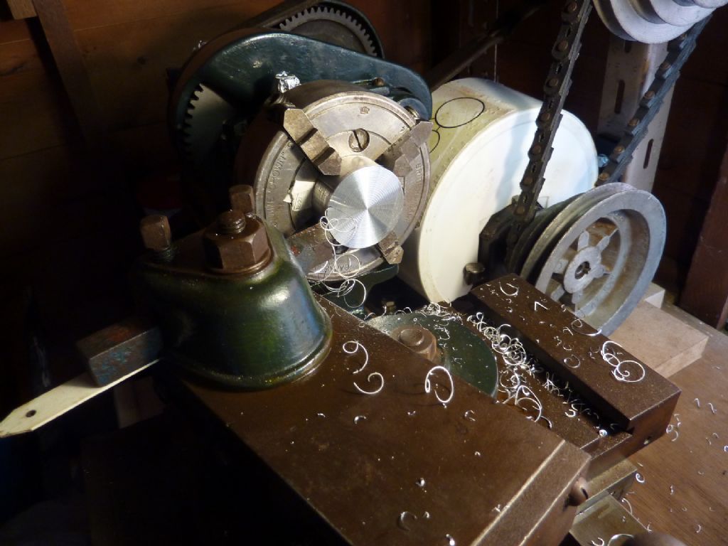
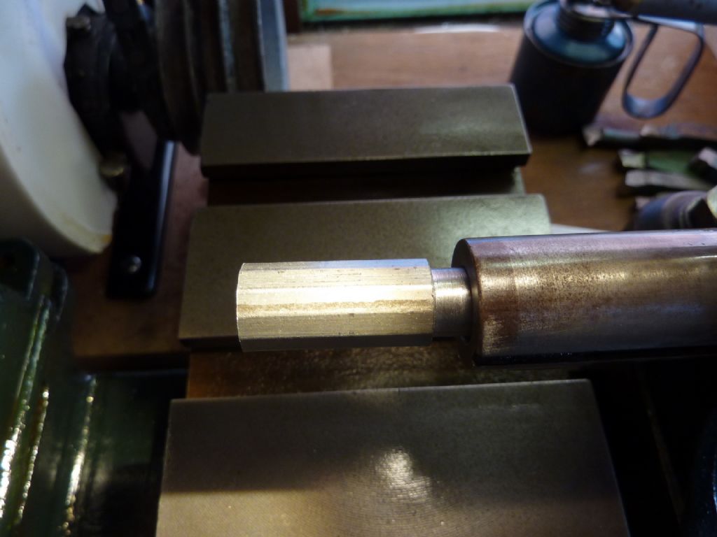
              The first real job is an aluminium handwheel cup for my MF70 CNC conversion. The first operations are to face off my horrid hacksawing and then turn down the end to make a stub to engage in the shaft coupler. I'm using the big ESC tool bit for that but found it was maybe 0.5mm above centre which was tricky since it was clamped to the top of the compound and there was nothing I could remove to make it lower. After rummaging around the immediate area in the shed I found a bit of plant pot label and used this to shim the tool underneath just the rear clamp screw. Not pretty but it got the tool onto the centre height. Other than using a less agricultural material I can't think of a better answer just now because the top face of the tool has obviously been profiled during manufacture and I would be very reluctant to lose this.

              The next operation will be boring out a blind hole for the handwheel on the other side. This may prove tricky – I have an Arc Euro 6mm boring tool that could quite happily to do this on my Cowells lathe but I really want to try to do it on the Faircut. Whether I can mount the small tool on the Faircut or else find another way remains to be seen.

              There is plenty more cleaning to do but this is mostly cosmetic or else related to bits of tooling that I don't need to use on day 1.

              p1070012.jpg

              p1070014.jpg

              #428570
              Steve King 5
              Participant
                @steveking5

                Looking good mate

                This is the sort of thread I was planning on doing with my faircut lathe before I came across the damaged headstock. Very interesting reading so far keep the progress updates coming. I still need to sort out the bits it's that you need as soon as I get five minutes in the garage I'll photograph what I've got an email them to you.

                Thanks

                Steve

                #428605
                Andy Carlson
                Participant
                  @andycarlson18141

                  Cheers Steve. Good to hear from you and thanks for the feedback. Will look forward to some photos when you have chance.

                  Regards, Andy

                  #429122
                  Andy Carlson
                  Participant
                    @andycarlson18141

                    I've been doing some more cleaning of the Faircut over the past couple of days.

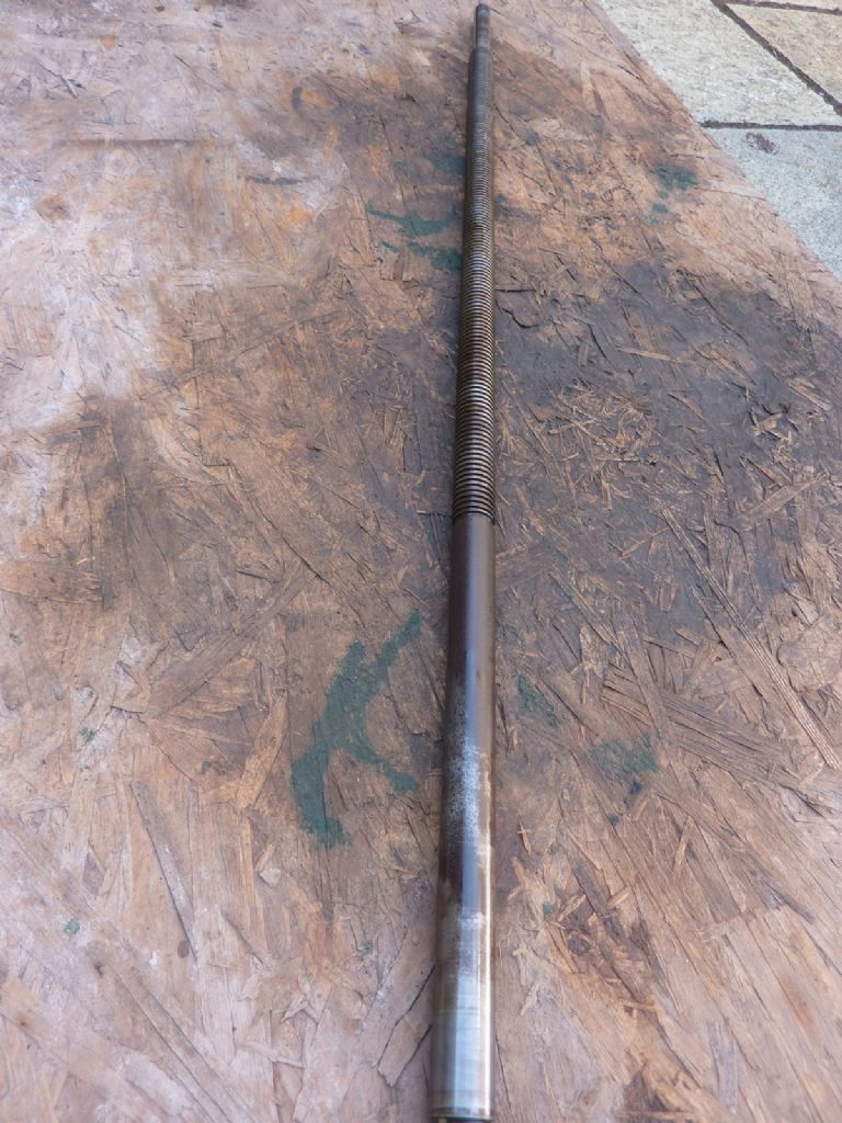
                    First job was the leadscrew – having a brown lead screw was really annoying me and having found while turning the handwheel cup for my MF70 CNC conversion that the leadscrew was stiff to turn at some parts of its rotation. I didn't need much more of an excuse to pull the thing out for cleaning. I'd describe the previous finish as polished rust and it proved quite resistant to being shifted using my usual recipe of citric acid. After several applications and scrubbing with a brass brush and a plastic kitchen scourer I ran out of time. It's a lot better but it still has 'freckles' and I will probably need to have another go.

                    p1070022.jpg

                    p1070025.jpg

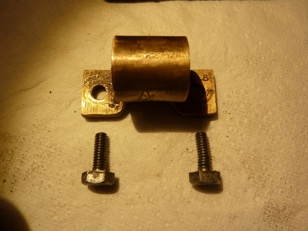
                    The leadscrew nut was also off for the first time since I got the lathe. If one of the bolts looks like it is kinked then that's because it is. I wonder what happened here – there seems to be no corresponding indentation in the hole in the nut. Very odd! I'm now in the market for a 1/4 BSF screw with a pre-war size of hex head. So far I have not found a source selling screws with the pre-war head size. Any ideas?

                    p1070027.jpg

                    The headstock taper is causing some puzzlement – I have tried several 1MT tools and they just grip on the thick end. They also stick out more that I would expect (same applies to the tailstock). As far as I know the taper is clean enough so I wonder if it really is 1MT. I'm not sure how to measure an internal taper with the tools at my disposal – the main one being a 1 inch external mike.

                    In better news I finally shifted the stuck gib screw out of the compound slide. After several days of trying WD40 I bought a can of an American product 'PPB Blaster' from eBay. After about 12 hours with this stuff the screw finally yielded. I think it's the correct thread but the thread peaks feel very rough. It's going in the bin and I will make a new one… which also means I'm in the market for a 3/16 BSW lock nut with the pre-war hex size.

                    Having relieved the compound casting of all of its fittings, I treated that to some citric acid today. I was expecting another protracted struggle but the rust came off very easily compared to the leadscrew.

                    p1070028.jpg

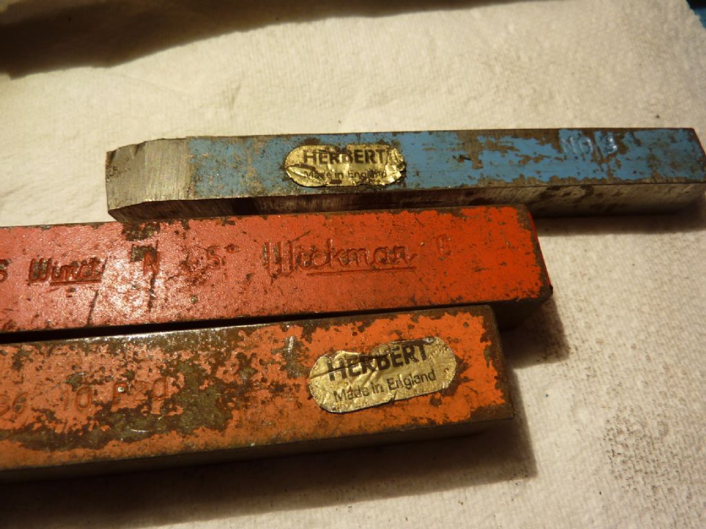
                    I bought some more tools from eBay. When they arrived I found some more names from the past. Interesting for me because my Dad worked as an external grinder at Herberts. Wickman is another famous Coventry name.

                    p1070026.jpg

                    #429124
                    not done it yet
                    Participant
                      @notdoneityet

                      Re the taper. I would measure accurately how far two different sized flat-ended (at least right angles at the circumference) circular rods will enter the socket. The distance between the two is calculated.

                      Now, knowing that distance between how far those two rods will go in and their diameters it is a simple mathematical calculation to find the tangent of the angle.

                      #429128
                      Andy Carlson
                      Participant
                        @andycarlson18141

                        Thanks. I did wonder if I could do something along those lines but I didn't figure out how to measure how far the rods had gone in.

                        Thinking about it some more I suppose I could move the tailstock ram up to the other end of the rod and then measure the gap once it's in the taper. My verniers would have to suffice for that because I think they are the only things that have sufficient travel.

                        Having some dials on the leadscrew or tailstock might make things easier but the lathe only has a dial on the cross slide.

                        Establishing a consistent starting point for both rods is another thing to think about – probably put some packing across the spindle nose and butt up against that.

                        Looks like I need to do some rummaging to find some suitable sized rods… and probably face them to make sure their ends are square.

                        #429139
                        Andy Carlson
                        Participant
                          @andycarlson18141

                          I tried a different approach which needed less preparation. The lathe came with several taper tools and I remembered that at least one of them did not stick out of the spindle so far. I tried this one again and it seems to grip the taper in a more convincing manner. Using some marker pen I found that the ink was rubbing off in places along the whole length of the taper.

                          I then took some external measurements on some of the tools. I used the vernier because then I could at least reasonably eyeball the how close to the end I was measuring but I doubt my results will be very accurate. It's also fair to say that the surface finish on these tools is not great.

                          For the best fitting centre I got a taper of 1:20.6 . For my Jacobs 1MT arbor I got 1:19.76 . A couple of others worked out at 1:19.19 and 1:19.98.

                          Conclusion… some of the tools that came with the lathe are in the right area for 1MT. If the internal taper really is somewhere around 1:20.6 then this would explain why the 1MT tools dont grip very well.

                          I was wondering if the taper was to a different standard but I cant find any standard taper that fits 1:20.6 so at the moment it looks like the spindle taper simply has a shallower angle than it should.

                          It would have been nice if I had got closer to the right answer (1:20.04) for the Jacobs arbor so maybe this is telling me that my measurements are not particularly accurate.

                          I need to do more checks before deciding what to do.

                          The thick ends vary between 12.05 and 12.30mm which is probably enough to explain the overhang – 0.25mm on diameter is 5mm extra on the overhang. I don't think this is telling me anything about whether the taper is right or wrong.

                          #430119
                          Andy Carlson
                          Participant
                            @andycarlson18141

                            I got around to doing some more measurements on my tapers, this time by making some bars of known diameter and measuring how far they go in. The results are pretty clear and don't make happy reading.

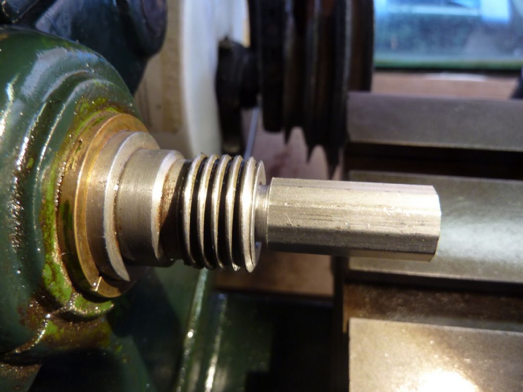
                            The basic setup is as per the photo – I used one of my die holders from the Cowells as a 'pusher' and then measured between the spindle end and the die holder using vernier calipers. I also measured with a ground piece of tool steel bridging the taper bore to get a starting datum for each bar.

                            p1070033.jpg

                            I took several measurements and reset each setup a few times to reduce any errors.

                            I won't try to post tables of numbers on here but after doing the maths, I got the following

                            Headstock taper: 1 in 24.1
                            Tailstock taper: 1 in 20.9

                            Now there is plenty of room for error in the making of my bars and the measurement setup, but it's clear that these numbers are miles apart. I re-checked them after I did the sums
                            and while the actual numbers may be subject to doubt, the difference between them is not.

                            Most of the measurements came out very similar for both headstock and tailstock but one did not namely how far the smaller bar entered each taper. The difference is obvious in the two photos below.

                            p1070034.jpg

                            p1070035.jpg

                            MT1 should be 1 in 20.04 so both tapers are shallower than they should be which agrees with my observation that a hopefully reliable Jacobs arbor only grips at the fat end.

                            The headstock number is pretty close to a Brown and Sharpe taper. I have no idea where and when B&S tapers were used but the fact that the tailstock taper is closer to MT1 rather persuades me that the headstock taper is just plain wrong.

                            So now what? My guess is that the headstock taper at least is too far wrong for the finishing reamers sold by the usual suppliers to rectify it.

                            #430204
                            Michael Gilligan
                            Participant
                              @michaelgilligan61133
                              Posted by Andy Carlson on 23/09/2019 12:59:56:

                              [ … ]

                              The headstock number is pretty close to a Brown and Sharpe taper. I have no idea where and when B&S tapers were used but the fact that the tailstock taper is closer to MT1 rather persuades me that the headstock taper is just plain wrong.

                              So now what? My guess is that the headstock taper at least is too far wrong for the finishing reamers sold by the usual suppliers to rectify it.

                              .

                              Headstock taper certainly sounds closer to Brown & Sharpe than anything else.

                              Surprisingly … reamers are available here: **LINK**

                              https://www.lasaero.com/products/article/U01D810Q7

                              So presumably B&S taper pins hold aircraft together.

                              MichaelG.

                              #430208
                              Andy Carlson
                              Participant
                                @andycarlson18141

                                Yes, thanks. I found that site when I was googling around. At the moment I'm not sure that reaming the headstock to a B&S taper would move things forward by much.

                                I struggle to believe that a lathe would be built with a B&S taper in the headstock and a Morse in the tailstock.

                                Like I said, I don't know much about B&S tapers. From what I can gather they date from the 1930s so the time is about right but B&S were a US outfit and they made milling machines. Finding a US milling machine taper on a British made lathe on which every screw fixing seems to be Whitworth or BSF seems hard to believe.

                                It would be interesting to know if B&S tapers were used on lathes, for example can a B&S dead centre be obtained?

                                At the moment I'm thinking that using a Morse finishing reamer on the tailstock taper may be the way to go. The headstock remains more of a conundrum. Not the end of the world but a bit annoying.

                                #430210
                                Michael Gilligan
                                Participant
                                  @michaelgilligan61133
                                  Posted by Andy Carlson on 23/09/2019 22:47:11:

                                  I struggle to believe that a lathe would be built with a B&S taper in the headstock and a Morse in the tailstock.

                                  [ … ]

                                  It would be interesting to know if B&S tapers were used on lathes, for example can a B&S dead centre be obtained?

                                  .

                                  I don't … and yes

                                  **LINK**

                                  https://www.starkindustrial.com/brown-and-sharpe-taper-standard

                                  That said: I think it might be preferable to grasp the opportunity and adapt the headstock to take collets.

                                  MichaelG.

                                  #430211
                                  Andy Carlson
                                  Participant
                                    @andycarlson18141

                                    Yes, I really should look before I post

                                    The options at the moment seem to be US based.

                                    I guess there is always the alternative of making an unhardened one myself. It always takes me a while to twig that as a lathe owner, I can do that kind of thing.

                                    That would solve the turning between centres issue but the lathe also has a vertical milling slide which begs the question of how to hold a milling cutter or drill.

                                    The one (damaged) cutter that came with the lathe is an old US made one with an integral taper. I didn't measure this last week but given today's conclusions, I just did. I got the taper to 1:20.07 which is pretty much spot on for MT1.

                                    My guess is that the original owner of the lathe believed the headstock to have an MT1 taper – even the most 'wrong' taper tool that I measured was 1:20.6 (which grips the tailstock well). I doubt whether anything gripped the headstock taper very well though.

                                    #430214
                                    Andy Carlson
                                    Participant
                                      @andycarlson18141
                                      Posted by Michael Gilligan on 23/09/2019 23:04:19:

                                      Posted by Andy Carlson on 23/09/2019 22:47:11:

                                      That said: I think it might be preferable to grasp the opportunity and adapt the headstock to take collets.

                                      Long term I may well fit a collet chuck to the spindle nose thread but that will take time to do properly and I was hoping to be able to hold milling cutters and drills without going to those lengths. I have bought a cheap chinese ER16 holder which is MT1 at the back end. Seeing how badly that fitted into the spindle is how I got started on the taper investigation.

                                      Going to those lengths will also throw up the dilemma of whether to fit an ER16 holder for which I already have a collet set or invest a good deal more money and buy another set of bigger collets… which is kinda why I want to avoid that question.

                                      #430215
                                      Michael Gilligan
                                      Participant
                                        @michaelgilligan61133

                                        I was actually thinking of boring-out the mystery taper and using draw-in collets

                                        … But it's your lathe.

                                        Good luck with whatever you decide to do. yes

                                        MichaelG.

                                        #430230
                                        Andy Carlson
                                        Participant
                                          @andycarlson18141
                                          Posted by Michael Gilligan on 23/09/2019 23:50:14:

                                          I was actually thinking of boring-out the mystery taper and using draw-in collets

                                          … But it's your lathe.

                                          Good luck with whatever you decide to do. yes

                                          Thanks Michael and thanks for your advice. I am thinking that if I take the boring tool to the spindle then it would be to bring the taper close enough to the correct angle for MT1 so that I could use a reamer. I would still need to check to make sure that this wouldn't leave the tooling too deep inside the spindle. My calculation is that the fat end would need to be 9.4 thou bigger diameter and the tooling would then be 4.8mm deeper into the taper which is quite a lot. At the moment I'm thinking it might be best to put this issue further down the queue and spend a bit longer thinking about it.

                                          #430667
                                          Andy Carlson
                                          Participant
                                            @andycarlson18141

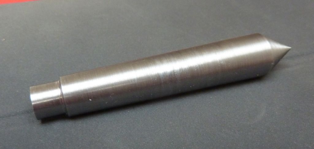
                                            Yesterday evening I turned up a new soft centre to the measurements I'd taken from the headstock taper.

                                            p1070049.jpg

                                            After some trial and error I think I hit the calculated taper angle to within the accuracy that I can achieve but that might still not be the right answer…

                                            The pointy end was turned down with the centre in the headstock once the taper had been done. Once I was past half way through this process I found that the centre was regularly breaking loose and it became rather a frustrating exercise for a while.

                                            As the job progressed I spotted a problem – the cutting tool was slightly above centre (in my defence, bear in mind that up to this point I only had MT1 centres that did not fit the spindle properly and had visible runout at the tip). I corrected this and was able to complete the pointy end without any more breaking loose. I also pop marked it so that I can put it back in the spindle in the same position next time.

                                            So how well does it fit? Initially it seemed to grip very well but the breaking loose did not inspire confidence. All of that mucking about has, however burnished the turning marks to show me where it is gripping and where it is not. The result surprised me a little.

                                            The taper is roughly 2 inches long. At the thick end there is perhaps 1/4 inch which is inside the spindle taper but has not burnished. Then about an inch that is burnished. The remaining part of the thin end has much less burnishing.

                                            This result puzzled me – I was expecting it to grip at either the thick end or the thin end depending on whether my angle was to steep or too shallow… but in fact it is gripping in the middle and at neither end. My theory to explain this is as follows…

                                            The actual machined taper in the headstock is shallower than the taper on the centre but repeated use of MT1 tooling by a previous owner has worn the first 1/4 inch or so into a steeper taper. The upshot of this is that my measurement inside the taper was also wrong because the 'fat end' measurement was measuring inside the worn part.

                                            At the moment I'm thinking that having an inch of the fattest usable part of the taper engaged is not so terrible for a dead centre so I'm not intending to have a second attempt. This should at least allow me to accurately set tools to centre height and do a much better check on the tailstock alignment than I've been able to manage so far.

                                            The tailstock definitely aims low – that is clear from the behaviour when centre drilling but my previous attempts to check the alignment with two centres was inconclusive.

                                            Given my conclusions about the state of the headstock taper I will abandon any thoughts of making a drill chuck arbor to fit. It will either be a collet chuck on the spindle thread or else re-machining the taper to MT1. I have no plans to attempt to machine the taper though until I have had a lot more practice at machining tapers accurately.

                                            #430736
                                            not done it yet
                                            Participant
                                              @notdoneityet

                                              Posted by Andy Carlson on 27/09/2019 08:44:09

                                              I have no plans to attempt to machine the taper though until I have had a lot more practice at machining tapers accurately.

                                              A good plan. Achieving the correct angle is easy enough – although perhaps tedious. Cut a socket (or more) and check with a known good Morse taper using engineer’s blue until you are confident the angle is exactly what is required. It is then only a case of attaining a good finish on the spindle and of the correct diameter at the nose.

                                              BTW, any centre cut in the lathe chuck, should be as good as you can achieve by any other means – until you remove it from the chuck.

                                              #430766
                                              Andy Carlson
                                              Participant
                                                @andycarlson18141

                                                Posted by not done it yet on 27/09/2019 13:59:18:

                                                A good plan. Achieving the correct angle is easy enough – although perhaps tedious. Cut a socket (or more) and check with a known good Morse taper using engineer’s blue until you are confident the angle is exactly what is required. It is then only a case of attaining a good finish on the spindle and of the correct diameter at the nose.

                                                BTW, any centre cut in the lathe chuck, should be as good as you can achieve by any other means – until you remove it from the chuck.

                                                I've ordered an MT1 finishing reamer to clean up the tailstock taper. When I get to the headstock taper I will use the finishing reamer after boring. I need 9.4 thou more diameter at the fat end to correct the taper but it's currently 11.7mm (0.460 in) so 15 thou below nominal size for MT1. The tailstock taper is also 11.7mm at the mouth, but apart from cleaning up the taper I will leave it below size.

                                                I hope that the custom tapered soft centre will solve several issues – I can now set the tool height with more certainty and should be able to assess the tailstock alignment once my order for a new (and not blunt) MT1 centre arrives.

                                                #430776
                                                old mart
                                                Participant
                                                  @oldmart

                                                  I was amazed to see that a motor manufactured in the USA some time ago would have a temperature in centigrade on it, even now they are the last bastion of Fahrenheit.

                                                  #430785
                                                  SillyOldDuffer
                                                  Moderator
                                                    @sillyoldduffer
                                                    Posted by old mart on 27/09/2019 18:09:07:

                                                    I was amazed to see that a motor manufactured in the USA some time ago would have a temperature in centigrade on it, even now they are the last bastion of Fahrenheit.

                                                    Well spotted! As the motor is also 50Hz and does 240V, I guess it was made for the UK market, not the USA. WW2 Lend Lease perhaps?

                                                    #430790
                                                    Andy Carlson
                                                    Participant
                                                      @andycarlson18141
                                                      Posted by SillyOldDuffer on 27/09/2019 18:57:42:

                                                      Posted by old mart on 27/09/2019 18:09:07:

                                                      I was amazed to see that a motor manufactured in the USA some time ago would have a temperature in centigrade on it, even now they are the last bastion of Fahrenheit.

                                                      Well spotted! As the motor is also 50Hz and does 240V, I guess it was made for the UK market, not the USA. WW2 Lend Lease perhaps?

                                                      I thought that strange but there are plenty of these motors still around in the US. Even the US ones have the temperature rise quoted in centigrade. The US ones are usually 110/220V and 60Hz. Several UK ones are 110/220V and 50Hz. I'm not sure that I've seen another 240V one so far.

                                                      The motor is hard to date but is definitely between 1915 and 1937. My suspicion based on design variations from similar motors is that it is around the middle 1920s. It is definitely older than the lathe so I suspect it was acquired second hand by the chap who bought the lathe new.

                                                      For anyone interested in donkeys' ages old motors, there is a Facebook group called 'Antique Electric Motor Experts'.

                                                    Viewing 25 posts - 26 through 50 (of 90 total)
                                                    • Please log in to reply to this topic. Registering is free and easy using the links on the menu at the top of this page.

                                                    Advert

                                                    Latest Replies

                                                    Home Forums Manual machine tools Topics

                                                    Viewing 25 topics - 1 through 25 (of 25 total)
                                                    Viewing 25 topics - 1 through 25 (of 25 total)

                                                    View full reply list.

                                                    Advert

                                                    Newsletter Sign-up