Stuart Twin Victoria (Princess Royal) Mill Engine

Advert

Stuart Twin Victoria (Princess Royal) Mill Engine

Home Forums Work In Progress and completed items Stuart Twin Victoria (Princess Royal) Mill Engine

Viewing 25 posts - 26 through 50 (of 1,125 total)
  • Author
    Posts
  • #506818
    Dr_GMJN
    Participant
      @dr_gmjn

      Ramon, can you direct me to where the cutters are for the bar please? I'd prefer to use carbide inserts. Is it a round section tool holder that would fit into the cross-hole?

      Advert
      #506829
      JasonB
      Moderator
        @jasonb

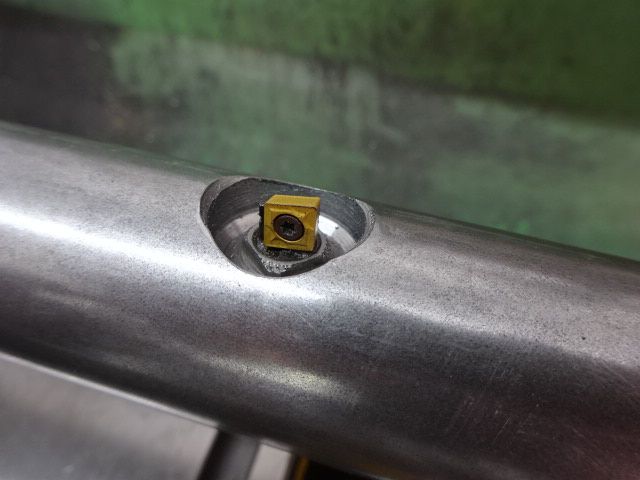
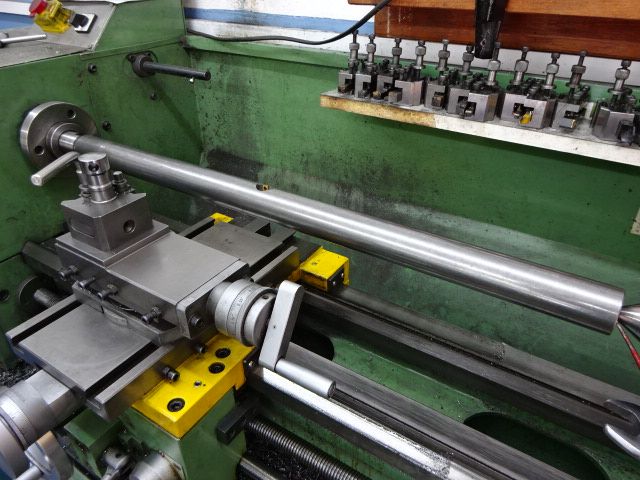
        You will be hard pushe dto find an insert holder to swing that small a radius, A piece of 3/16" dia HSS would be about the right size, maybe upto 1/4" dia. Old ctr drill or milling cutter shank will do nicely. I do habe an insert tool but that goes into my little 35mm dia bar

        There are three ways to go with the cylinder. 1. bore it out and face the piston end first then hold it on an arbor to machine the feet and port face. 2. Machine the feet, then portface on the mill before setting up on the cross slide to bore the cylinder. 3. Bore and face then set up in the mill using the face as the ref to do feet and portface.

        #506844
        peak4
        Participant
          @peak4
          Posted by Dr_GMJN on 01/11/2020 22:22:39:

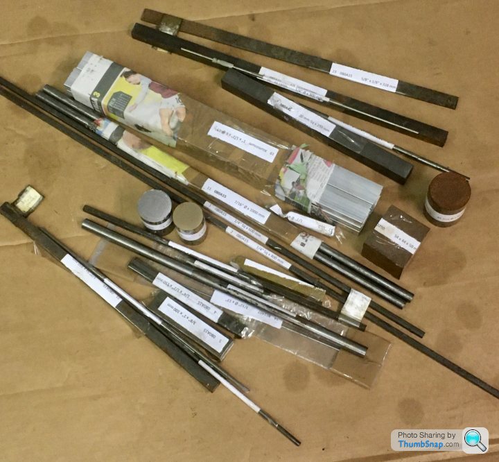
          I've opted to buy only the castings. I will fabricate the beds from aluminium, and make the rest from stock materials, which I've already got from a local supplier:

          A good range of bits there; if you don't mind me asking, who was your local supplier?
          As you know, I'm not far from you myself.

          Bill

          #506851
          Ramon Wilson
          Participant
            @ramonwilson3

            Well Doc, we all have differing ways to approach this subject and getting the feet true and parallel along with the valve face is critical as you surmise. Cat skinning is to the fore on this one.

            Personally I always do the bore first then use that as the datum to bring all other surfaces including the ends true to it – take a look here post 28 onwards or this one here post 24. The latter a much more complex casting for getting several surfaces and axis truly in relation. It's down to choice but I have always worked on the basis of what ever op is being done it should, if possible, lead to an accurate means for doing the next. Pays, money choice etc.

            I use HSS bits in my boring bars – somewhere though I have no idea where I have a few carbide tips set in a holder similar to Jasons but the tips are not replaceable. As said before I use discarded throw away cutter shanks for such purposes – excellent material and easily ground. I broke a 1.5 mm one this afternoon – the shank went straight in the cutter tin.

            You are seeking advice on here and you will recieve much – it is down to you to decide which suits your purpose best and choose accordingly. I offer mine based purely on my own previous personal experience which I hope will be of use – if not to yourself then perhasp some one looking in.

            Regards Ramon


            PS Cut short by tea time !! I have more cutter shanks than I require – if you want some just say so and I'll send you some.

            Edited By Ramon Wilson on 11/11/2020 19:22:04

            #506896
            Dr_GMJN
            Participant
              @dr_gmjn

              Thanks Ramon, I’ll fully digest all that later.

              What I’m trying to do is get some options together and go with the one(s) I feel most comfortable with. I stuck the 10V cylinder in a chuck and bored it out, simple! I know a between centres approach is probably better for these longer cylinders, so I’ll go with that despite it being totally new to me. I suppose fear of the unknown, and potentially scrapping a casting. Having said that, one of the 10V Cylinder faces was a bit out of true, so even that wasn’t so easy!

              Boring the cylinder first makes sense. I can put a mandrel in it and use that to get the axis, and offset from that vertically and horizontally for subsequent operations on the valve face and feet. I guess for the initial boring operation I could sit the casting on the cleaned-up valve face?

              Thanks for the kind offer of the tools. I do have some scrap milling cutters from my first attempts at milling earlier this year! Thanks anyway – I’ll see how I get on.

              #506900
              Dr_GMJN
              Participant
                @dr_gmjn
                Posted by peak4 on 11/11/2020 18:08:50:

                Posted by Dr_GMJN on 01/11/2020 22:22:39:

                I've opted to buy only the castings. I will fabricate the beds from aluminium, and make the rest from stock materials, which I've already got from a local supplier:

                A good range of bits there; if you don't mind me asking, who was your local supplier?
                As you know, I'm not far from you myself.

                Bill

                Yes, it’s Metals Procurement in Rotherham. Mark is the owners name. I think he is an ex steel works metallurgist. He knows his stuff and is very helpful. I did ask him if many customers are model engineers. He said that many years ago he put an advert in a M.E. Magazine and was inundated with requests for tiny amounts of material! I guess predictable, but I don’t think he bargained for the amount of calls. He said he still gets calls from the same advert – these people don’t throw magazines away! There are a few bits of round bar he couldn’t get, but the majority was no problem. The fact he’s only about 20 minutes away makes it very useful too! The whole lot shown there – stainless, silver, mild, aluminium, brass, gunmetal, cast iron) was about £70/£80.

                #506909
                Ramon Wilson
                Participant
                  @ramonwilson3
                  Posted by Dr_GMJN on 11/11/2020 21:50:29:

                  Thanks Ramon, I’ll fully digest all that later.

                  What I’m trying to do is get some options together and go with the one(s) I feel most comfortable with. I stuck the 10V cylinder in a chuck and bored it out, simple! I know a between centres approach is probably better for these longer cylinders, so I’ll go with that despite it being totally new to me. I suppose fear of the unknown, and potentially scrapping a casting. Having said that, one of the 10V Cylinder faces was a bit out of true, so even that wasn’t so easy!

                  Boring the cylinder first makes sense. I can put a mandrel in it and use that to get the axis, and offset from that vertically and horizontally for subsequent operations on the valve face and feet. I guess for the initial boring operation I could sit the casting on the cleaned-up valve face?

                  Thanks for the kind offer of the tools. I do have some scrap milling cutters from my first attempts at milling earlier this year! Thanks anyway – I’ll see how I get on.

                  You are at what I was faced with 45years ago – early days, so much to learn, so much to take in. The major difference of course was that the only way I could get help was via a monthly model club meeting – I well remember going from person to person asking if anyone could help me with trying to cut a thread on silver steel – each in turn referring me to someone else. Finally I gave up getting nowhere and struggled on with this most trying of machining but it would be quite a few years before I realised that the persons concerned probably didn't actually know anyway.

                  I became so enarmoured with machining I gave up a lucrative offshore career and retrained as a milling machinist. From that point on I until I retired I worked in three 'jobbing' shops and one in a factory environment, building up and running a machine shop. In all that time I never, save one item, machined anything that I couldn't lift on the machine myself. Every day was different in the jobbing shops and as you can imagine it was a steep learning curve – time is money and mistakes highly unpopular.

                  I say this because I have seen both sides of the fence – first as a rank amateur and second as having to earn a living. I have not forgotten how difficult it is to find your way in the early stages of ME hence my interest in helping those in similar circumstances but there are always many many ways of going about something – some good some not so – but the choice of how is very much down to the individual.

                  So, with regards to the cylinder – if the bore goes in first then yes you do need a good datum face and yes the ideal one is usually the valve face. (that face should not be taken down to finished dimension at this stage – merely cleaned up flat) Once that bore is finalised then all other faces are brought to it ideally by holding on a close fitting mandrel (not like the cylinder in the first link where it can sit slightly off set). It's far easier to check these faces to the bore and have time to make allowances if not quite right than by finding your bore is out to them if machined first and the only way it can be rectified is by making it larger, possibly having to sleeve it.

                  Expanding mandrels are very easy to make – they can be held in a chuck but if the back face is faced first and drilled and tapped it can then be bolted square to an angle plate if transfering to the mill is required and you don't have a means to support the chuck eg dividing head.

                  The discarded cutters I have all have 6mm or 1/4 inch shanks – offer's still open if they suit your purpose

                  Regards – Ramon

                  Edited By Ramon Wilson on 11/11/2020 23:21:44

                  #506915
                  peak4
                  Participant
                    @peak4
                    Posted by Dr_GMJN on 11/11/2020 22:04:23:

                    Yes, it’s Metals Procurement in Rotherham. Mark is the owners name………………..

                    Cheers for that, see also Phoenix Steels in Attercliffe for silver and tool steels, Canal St just off Effingham Rd.

                    and also AMB for stainless and alloy; their yard prices are better than the web prices; again not far away, a non descript gate on Washford Road.

                    Bill

                    #507323
                    Dr_GMJN
                    Participant
                      @dr_gmjn

                      Thanks all.

                      Thinking about the between centres boring bar: what’s the most accurate way of centering the ends, assuming it’s too large a diameter to fit through the spindle?

                      Ive not done anything between centres before, but I do have a drive plate/carrier. Should I mill a flat on the end for the carrier?

                      I realise at the moment there are a lot of questions and no progress on the model – I’m trying to get things worked out and tools ready before starting. The drawings for the bases are done and I have the material for them, they will be started first. Just waiting for the JB weld to arrive.

                      #507326
                      Steviegtr
                      Participant
                        @steviegtr

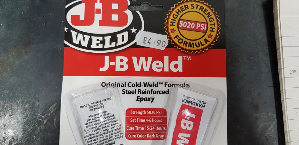
                        When i bought some JB weld they had various ones on the shelf. This one was rated the strongest, but not sure as it is the 1st time i have used it. It was the figures they gave that prompted me to go for this one.

                        Steve.

                        j b weld.jpg

                        #507329
                        Ramon Wilson
                        Participant
                          @ramonwilson3

                          If the bar won't go up the spindle its best to use a fixed steady if you have one. If not insert it in the chuck as deep as it will go and nip up but not over tight. Gently tap the outer end to tweak the concentricity – it's not that important as long as it's reasonable – and gently start the centre drill – once it has a start then drill as normal. Reverse and do the other end and yes ideally mill a small flat for the carrier. Set between centres and where you intend to have the cutter placed turn down the minimum to achieve a concentric surface about an inch wide. Transfer to the mill for the cutter hole and grubscrew hole – as said before make the cutter hole blind if you want the means to adjust the cutter in very small amounts.

                          Getting started on the model isn't a factor at the moment. Keep on doing what you are – preparing the ground and asking questions so when you do you are ready for it


                          Stevie – that is the strongest (and the slowest cure) the other versions do not have the same strength or temperature characteristics.


                          Regards – Ramon

                          Edited By Ramon Wilson on 13/11/2020 23:15:06

                          #507397
                          Dr_GMJN
                          Participant
                            @dr_gmjn

                            OK. So in terms of aligning the cylinder on the cross-slide, ready for boring, I'm thinking of turning a hardwood plug, and centering each end of that, then tapping it into the cast bore. I can then use the vernier points to make sure the outside of the casting ends are more or less concentric with the bore (as with teh 10V). It will make machining the cast O/D's more consistent for fitting whatever cladding I decide on. I can then use the head and tailstock centres to make sure it's aligned before clamping everything down. I suppose it would be good to tighten the cross slide gibs as well?

                            On the cladding – I'm not sure whether to stick with aluminium, or try wooden strips. I like aluminium better, but it seems like a tricky job to cut it to the cylinders, what with the feet and valve blocks etc.

                            #507409
                            Ramon Wilson
                            Participant
                              @ramonwilson3
                              Posted by Dr_GMJN on 14/11/2020 12:51:05:

                              OK. So in terms of aligning the cylinder on the cross-slide, ready for boring, I'm thinking of turning a hardwood plug, and centering each end of that, then tapping it into the cast bore. I can then use the vernier points to make sure the outside of the casting ends are more or less concentric with the bore (as with teh 10V). It will make machining the cast O/D's more consistent for fitting whatever cladding I decide on. I can then use the head and tailstock centres to make sure it's aligned before clamping everything down. I suppose it would be good to tighten the cross slide gibs as well?

                              How do you intend to hold it ? Do you have an angle plate or vertical slide?

                              Yes lock the gib screws

                              #507421
                              Dr_GMJN
                              Participant
                                @dr_gmjn

                                I was just going to remove the top slide assembly, and block it up directly from the cross-slide t-slot table. It would sit either on it's feet, or on the valve face (I'd have flatted it with a file and on the surface plate, ready for final machining later). Then clamp it with a bar (or two) over the top.

                                If I've understood correctly, I progressively move the cutter out from the bar until I get to the right diameter – The cylinder itself only moves left to right by means of the saddle?

                                #507422
                                JasonB
                                Moderator
                                  @jasonb

                                  That sounds to be the way Westbury did it on packing clamped to the cross slide a method I have used on several cylinder. Do think ahead as to how you will machine at least the piston end of the cylinder's end flange square to the bore and also how you will do the final finishing of the feet and port face.

                                  Don't know if I dare suggest flycutting the end of the cylinder while it's still undisturbed and attached to the topslidewink 2

                                  If I did the fabricated version I would hold in 3 or 4-jaw (not sure which will fit) to bore and face one end and then machine everything relative to those surfaces.

                                  Edited By JasonB on 14/11/2020 13:42:28

                                  #507475
                                  Dr_GMJN
                                  Participant
                                    @dr_gmjn
                                    Posted by JasonB on 14/11/2020 13:23:50:

                                    That sounds to be the way Westbury did it on packing clamped to the cross slide a method I have used on several cylinder. Do think ahead as to how you will machine at least the piston end of the cylinder's end flange square to the bore and also how you will do the final finishing of the feet and port face.

                                    Don't know if I dare suggest flycutting the end of the cylinder while it's still undisturbed and attached to the topslidewink 2

                                    If I did the fabricated version I would hold in 3 or 4-jaw (not sure which will fit) to bore and face one end and then machine everything relative to those surfaces.

                                    Edited By JasonB on 14/11/2020 13:42:28

                                    I'm happy to do the bore and facing in the 4 jaw chuck, as with the 10V.

                                    I thought the whole point of the boring bar between centres was that it's more accurate for longer cylinders? Then again is it really that different than the 10V – it appears to work fine? Seems far easier to do in the chuck assuming it can be held in there.

                                    I'll still use fly cutting for as much as I can – I really dislike the look of a milled surface, at least the ones I do!

                                    I didn't know there was a fabricated version. Do you mean as in milled from solid bar?

                                    #507486
                                    JasonB
                                    Moderator
                                      @jasonb

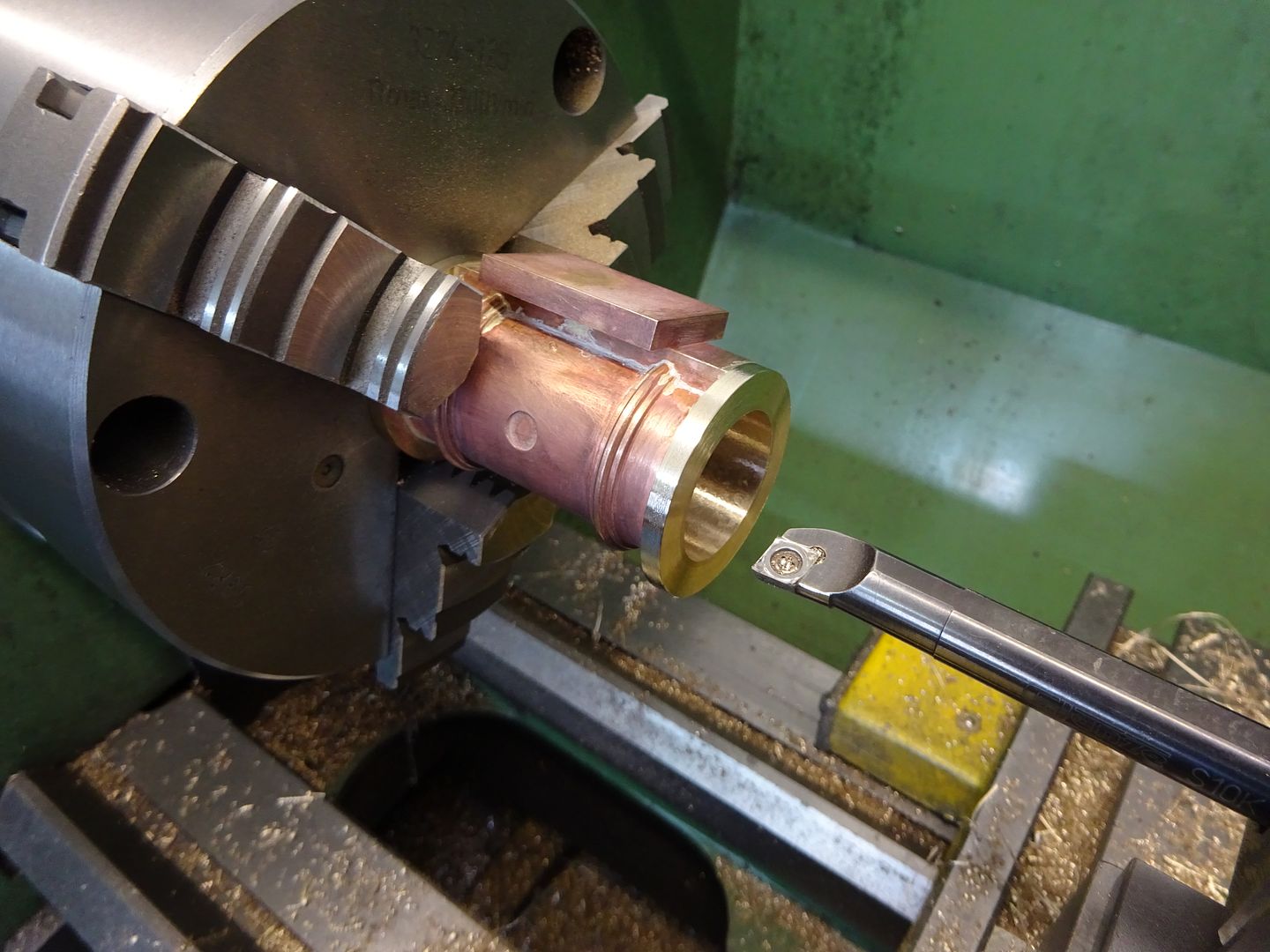
                                      A lot will depend on how the individual machine bores, I would certainly have to take care to get it parallel and probably opt to do the last few passes with HSS as inserts can tend to get pushed off the surface more though **GT ones will reduce the tendency. Any slight taper can often be honed or lapped out. But as you say between ctrs should give a parallel bore. The longer the bore the more likely it is to taper as you have more of a standard poring bar hanging out the toolpost.

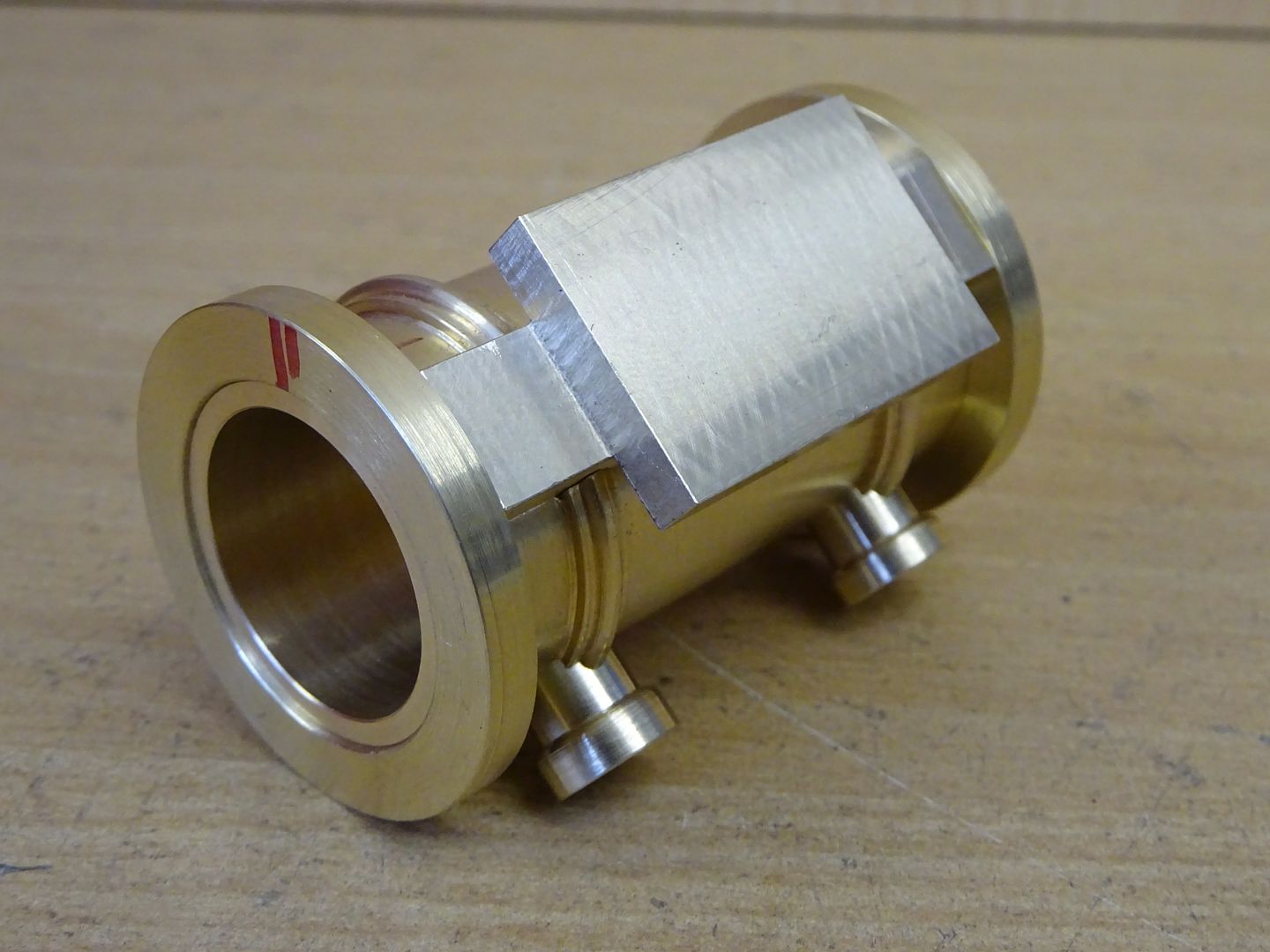
                                      Fabricated cylinders make it a bit easer to know that the end of the bore in the chuck is running true before you start but there are ways to make it easier with castings.

                                      The one I had started to draw up would have been with fabricate dcylinders

                                      twin vickys.jpg

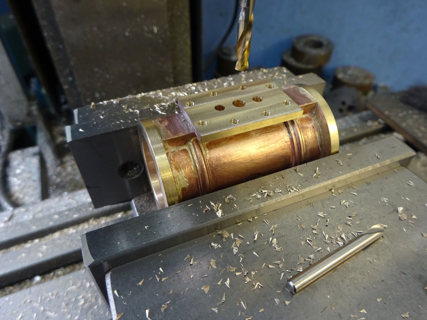
                                      basically soldered up from brass and bronze

                                      Bored after soldering and pickling

                                      faces milled

                                      #507500
                                      Dr_GMJN
                                      Participant
                                        @dr_gmjn

                                        Nice work.

                                        How about with Ramon's PTFE rings? In practical terms is it going to matter about a very slight taper?

                                        I'll probably try the between centres approach, just for the sake of it.

                                        By the way – what is the usual way of aligning and fixing the cylinder if not on the cross slide t-slot bed?

                                        #507505
                                        Ramon Wilson
                                        Participant
                                          @ramonwilson3

                                          Packing it up from the bed is just fine – holding it to an angle plate or vertical slide allows infinite vertical adjustment but packing of the right height is okay. One thing to really take note of is not over tightening the clamps – not quite so important with cast iron as it is bronze but if you do distort it then the bore will be distorted once the clamps are released. This is one op where that simple slip of paper between the part and clamping surface pays dividends.

                                          If you make yourself an expanding mandrel as has already been suggested you can do both ends of the cylinder as normal facing operations absolutely square to the bore – no fly cutting required. Move that to the mill and you can do all the other ops from the centre line of that mandrel – either still in the lathe chuck if you have a dividing head or as already suggested too bolted to an angle plate or even a piece of steel held vertical in the milling vice.

                                          Doing the bore from the chuck is just as practical but you do run the risk of a taper – not much I grant you and yes you can lap it out but that's more tooling and another op.

                                          If you took a look at the link I posted you will have seen what I mean about a mandrel – once you make these and get used to working with them you will realise just how useful they are. It's much better to make your own. I have a set bought from Arc Euro – they've never been used because they are never quite right size wise.

                                          Any way you are In Jason's good hands so I'll bow out now – too many cooks etc – will end up getting you confused

                                          Good luck with your build – I may be joining you soon

                                          Regards – Ramon

                                          #507507
                                          Dr_GMJN
                                          Participant
                                            @dr_gmjn

                                            I appreciate your input as I do Jason's – I try to take the bits from both that I'm most comfortable with doing; I know all the advice is sound, any errors arising in the past have been through my own mis-interpretation.

                                            I had planned on using an expanding mandrel in order to find the finished bore axis in the mill – with the centre finder. I may have to reduce the end to a diameter that the finder tip can get to.

                                            I can then offset directly from the axis to setup for the fabricated feet edges, and in the other plane, for the feet and valve pad heights.

                                            #507515
                                            Ramon Wilson
                                            Participant
                                              @ramonwilson3

                                              Take no offence Doc – but as it is confusing to have several inputs possibly in conflict at times I thought it might be for the best.

                                              I've always advocated 'listen to all' but 'make your own decision from what you've heard' – as you no doubt are aware that applies to plastic modelling as well as ME but too much information can become confusing especially for someone relatively new.

                                              I think I said before we all have differing techniques to achieve an end result – you have to decide which best suits your purpose, your equipment and knowledge.

                                              As said mandrels make for much easier approaches to many machining ops. I can thoroughly recommend you investigate their usefulness wink

                                              BTW the mandrel should be within the cylinder. Find the centreline of it on the mill before putting the cylinder on it

                                              Regards – Ramon

                                              #511594
                                              Dr_GMJN
                                              Participant
                                                @dr_gmjn

                                                Quick update – I ordered the main castings yesterday. I've not started on the fabricated base yet becasue I've been distracted with machine fettling (and to be honest I lost interest in that half way through for various reasons), and it's very cold in the garage these days. I'll order the fasteners next month, then that'll be all the main components sorted out.

                                                #512570
                                                Dr_GMJN
                                                Participant
                                                  @dr_gmjn

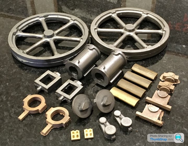
                                                  Well that’s about £300 of Stuart castings:

                                                  no going back now…

                                                  #513700
                                                  Dr_GMJN
                                                  Participant
                                                    @dr_gmjn

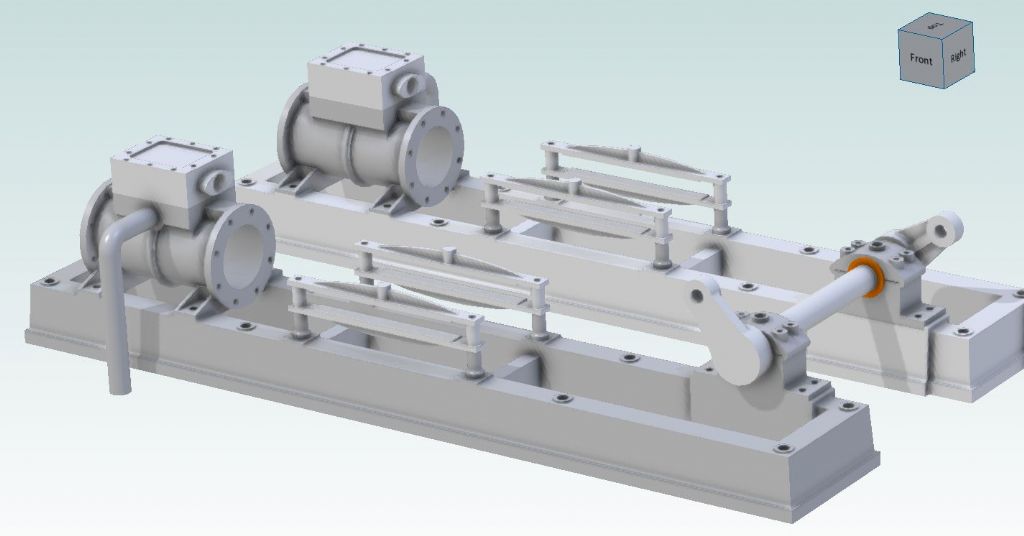
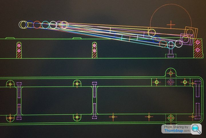
                                                    Been working a bit more on the soleplate CAD. Also spent some time verifying the geometry of the piston stroke/crosshead location/connecting rod etc:

                                                    Crank centreline works out spot on the same height as the cylinder axis, and the mid-stroke crosshead position is exactly half way between the guide rail hole centres, so my imperial/metric conversion must have been correct.

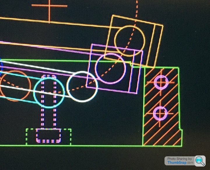
                                                    Looks like there's a clash with the big end bearing cap if using the original casting dimensions though, so I'll have to extend the sides a bit:

                                                    Better to find out now than when assembling it…I do seem to remember someone somewhere mentioning this issue with the connecting rod, and the casting needing a slot filing in it. I thought they meant the rod itself clashed with a soleplate cross brace. I've seen a video online where it looks perilously close, which is why I shortened them, but they must have meant the bearing cap.

                                                    #513708
                                                    Ramon Wilson
                                                    Participant
                                                      @ramonwilson3

                                                      Hi Doc G,

                                                      The big end will need a groove milled or filed in the end brace unless, as you say, you extend the sides a small amount.

                                                      Depends on how you feel about the aesthetics but to have a groove does follow full size practice as many bedplates have 'scallops' cast in for clearance around the rod movement.

                                                      'Perilously close' ? – a couple of thou gap is sufficient if there's no play in the moving parts – which is definitely the case on the Waller engine built – 'a miss is as good as a mile' springs to mind there wink

                                                      Regards – Ramon

                                                    Viewing 25 posts - 26 through 50 (of 1,125 total)
                                                    • Please log in to reply to this topic. Registering is free and easy using the links on the menu at the top of this page.

                                                    Advert

                                                    Latest Replies

                                                    Viewing 25 topics - 1 through 25 (of 25 total)
                                                    Viewing 25 topics - 1 through 25 (of 25 total)

                                                    View full reply list.

                                                    Advert