HAROLD halls TOOL REST

HAROLD halls TOOL REST

Home Forums Beginners questions HAROLD halls TOOL REST

  • This topic has 18 replies, 12 voices, and was last updated 5 May 2013 at 20:16 by Harold Hall 1.
Viewing 19 posts - 1 through 19 (of 19 total)
  • Author
    Posts
  • #118381
    Brett Hurt
    Participant
      @bretthurt41827

      In workshop series book 35 page 85 how does this all go together, like the lower slide. How does the lead screw work in it I need picturess of it.. Iam building the one on page 76 and need to know it all works. thanks

      #6693
      Brett Hurt
      Participant
        @bretthurt41827

        I HAVE A PROBLEM

        #118386
        JasonB
        Moderator
          @jasonb

          There should be some photos on Harold's site and hopefully he will also respond.

          J

          #118389
          Chris Trice
          Participant
            @christrice43267

            “… need to know it all works”. If I was Harold, I wouldn’t feel offended by that comment at all.

            #118390
            wheeltapper
            Participant
              @wheeltapper

              Hi

              Not having the book I don't know which one you mean, if its the simple one there are a lot of pics in my album that might help.

              If its the more complicated one you'll have to hope Harold answers.

              Roy.

              #118393
              Sub Mandrel
              Participant
                @submandrel

                Not aiming this comment at Harold (whio is not averse to including little explanatory sketches), but as a general principle there does often seem to be a lack of detailed general arrangements or assembly drawings for many devices and models. It is often the case that you have to know HOW something works before you can really understand how it fits together. Example – all plans for steam engines detail the parts of the valve, but without a cross section how does a beginner work out how to assemble the parts?

                This seems to be especially true of steam engine designs, although I note LBSC often had little diagrams of "how to erect the…" which seem absent from many modern accounts. Perhaps we rely on photographs too much?

                Neil

                #118398
                Ziggar
                Participant
                  @ziggar

                  if you actually read the text included with the drawings/plans then it is all explained quite clearly

                  but you DO have to read the text

                  i made this rest as one of my very first projects with absolutely no experience and having only owned a small lathe and mill for a matter of weeks. everything went acording to plan and 'it all works' just fine because i read the text along with the plans, and didnt just jump into making the rest without doing the reading first. That is how the book is written to be used.

                  read the text with the plans and it will all work out just fine

                  Z

                  #118418
                  Russell Eberhardt
                  Participant
                    @russelleberhardt48058

                    Have a good look at the assembly drawing on page 78. It has all parts clearly marked with the drawing number for that part. If you have made the parts and have them in front of you it should be easy to see how they go together.

                    If you still have problems perhaps you could be more specific. What part are you having problems with?

                    Russell.

                    #118436
                    Robbo
                    Participant
                      @robbo

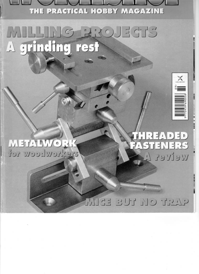
                      The Grinding Rest was originally an article in MEW 89, part of a series which Harold later turned into the book. The cover picture from that issue is shown below, as I think it is a better pic than those in the article.

                      There were machining instructions for each part, and plenty of drawings, including an assembly drawing.

                      Looking at these together, where's the problem?

                      Phil

                      grinding rest  by hh.jpg

                      #118452
                      Russell Eberhardt
                      Participant
                        @russelleberhardt48058

                        The only problem I have with mine is that in some positions the locking handles interfere with each other.

                        Russell.

                        #118453
                        roy entwistle
                        Participant
                          @royentwistle24699

                          Try instering washers under them till they don't interfere You may have to thin some of the washers

                          Roy

                          #118454
                          Brian
                          Participant
                            @brian

                            Thining washers? now thats another subject to be explored.

                            Brian

                            #118457
                            Russell Eberhardt
                            Participant
                              @russelleberhardt48058
                              Posted by Brian on 05/05/2013 10:05:40:

                              Thining washers? now thats another subject to be explored.

                              Simples, fix to the end of a bar in the lathe chuck with super-glue. When done immerse in boiling water to separate.

                              Russell.

                              #118458
                              Russell Eberhardt
                              Participant
                                @russelleberhardt48058
                                Posted by Brian on 05/05/2013 10:05:40:

                                Thining washers? now thats another subject to be explored.

                                Simples, fix to the end of a bar in the lathe chuck with super-glue. When done immerse in boiling water to separate.

                                Russell.

                                #118459
                                Russell Eberhardt
                                Participant
                                  @russelleberhardt48058

                                  Whoops – finger trouble again!

                                  #118469
                                  Robbo
                                  Participant
                                    @robbo

                                    The old way of avoiding a clash between the operating levers was to leave them until last. Assemble everything, tighten up the screws which are going to have levers, by whatever means possible, then mark the position for the levers so they don't clash.

                                    This is one of those things that you always remember when it's too late! For those of us who forget, Russell's washers are the answer.

                                    Phil

                                    #118473
                                    NJH
                                    Participant
                                      @njh

                                      "……..fix to the end of a bar in the lathe chuck with super-glue."

                                      or, even easier –

                                      Washers do not necessarily need to be thin. If you turn a piece of bar to the right diameter, drill the appropriate sized hole for the bolt then part off a slice thick enough to rechuck. Taking a bit off this allows several bites at getting the handles in the right position. You will find that removing quite a small amount makes quite a big difference.

                                      N

                                      #118496
                                      Harold Hall 1
                                      Participant
                                        @haroldhall1

                                        First an apology for being slow to respond but my internet connection was off line all day yesterday.

                                        I find it difficult to answer your question Brett as I am not sure just what you are looking for. However, here goes.

                                        The Lower Lead screw 3 passes through a hole at each end of the Lower slide 4 but is prevented from going right through due to the flange at the Feed knob 10 end. It is retained in position by a Nylock nut H2 which is also adjusted to eliminate back lash.

                                        The Lower Lead screw 3 is threaded through the Lower Lead screw nut 16 which is captive in one of the Slide Swivel Pieces 9.

                                        Therefore, turning the feed knob turns the Lower Lead screw causing the Lower lead screw nut to move along it. As this is captive in the Slide Swivel Piece this will move along the dovetails in the Lower slide.

                                        Does this answer your question.

                                        Do also read my comments in the next post.

                                        Harold

                                        #118498
                                        Harold Hall 1
                                        Participant
                                          @haroldhall1

                                          I would like, kindly, to offer a word of advice Brett.

                                          When starting a new project of mine you do need to take time to understand the assembly drawing and how the individual parts go together. To do the later, take adjacent parts and assemble them mentally, gradually building a picture as to how parts go together and function. Basically, this is what Ziggar is advising.

                                          Also, as Russell says, if you make the parts to the drawings then it will gradually become clearer as you start provisionally to put them together.

                                          Unfortunately, I am one of a few who provides fully detailed assembly drawings, many, only partial, or often non at all. In this case I could understand your problem.

                                          As an aside, some may be interested in my method of working.

                                          The first thing I do is to draw a full size, (digitally) assembly drawing. Then, only proceed from that if I am happy with the design and that all things will assembly correctly.

                                          From there, I cut and paste a small section of the assembly drawing often containing just one part. Of course this will include partial details of the surrounding parts which I erase leaving only the part I am about to detail.

                                          Most often, sections of the part will be hidden in the assembly drawing and appear as dotted lines. These are converted to solid lines and where a part passes through another there will be solid/dotted/solid sequence. rather than just changing the dotted to solid resulting in three lines I replace them by a single line from end to end.

                                          The above results in a part which is actual size when the CAD program can then automatically add the dimensions. Because of this dimensional errors on my drawings are very rare. Then of course, I go to the workshop and make the piece of tooling which largely proves the drawings.

                                          I just could not contemplate making something such as the grinding rest without drawings, then producing the drawings later for use in the magazine. I maybe wrong but I personally think that this is where many of the errors stem from.

                                          Back to Brett's Problem. I do accept that due to the size of the Workshop Practice Series books some of the drawings, especially assembly drawings, can be a little difficult to read.

                                          To help therefore in this case, I have added a pdf drawing of the more complex part of the rest that can then be printed out and more easily studied, being much larger than that in the book

                                          It can be found at **LINK** Listed as the “upper portion”. Hope this helps.

                                          Harold

                                        Viewing 19 posts - 1 through 19 (of 19 total)
                                        • Please log in to reply to this topic. Registering is free and easy using the links on the menu at the top of this page.

                                        Latest Replies

                                        Home Forums Beginners questions Topics

                                        Viewing 25 topics - 1 through 25 (of 25 total)
                                        Viewing 25 topics - 1 through 25 (of 25 total)

                                        View full reply list.