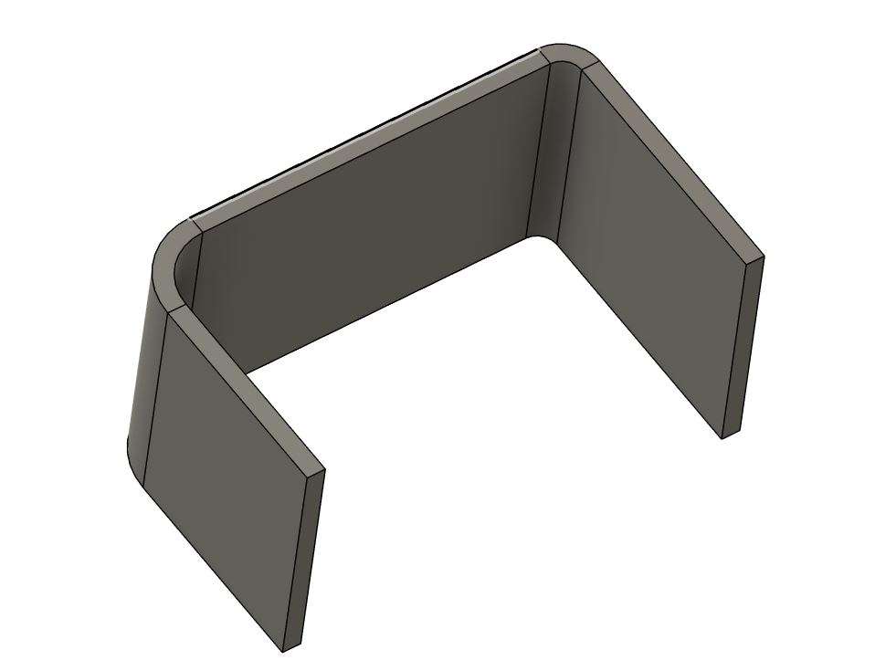
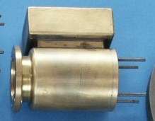
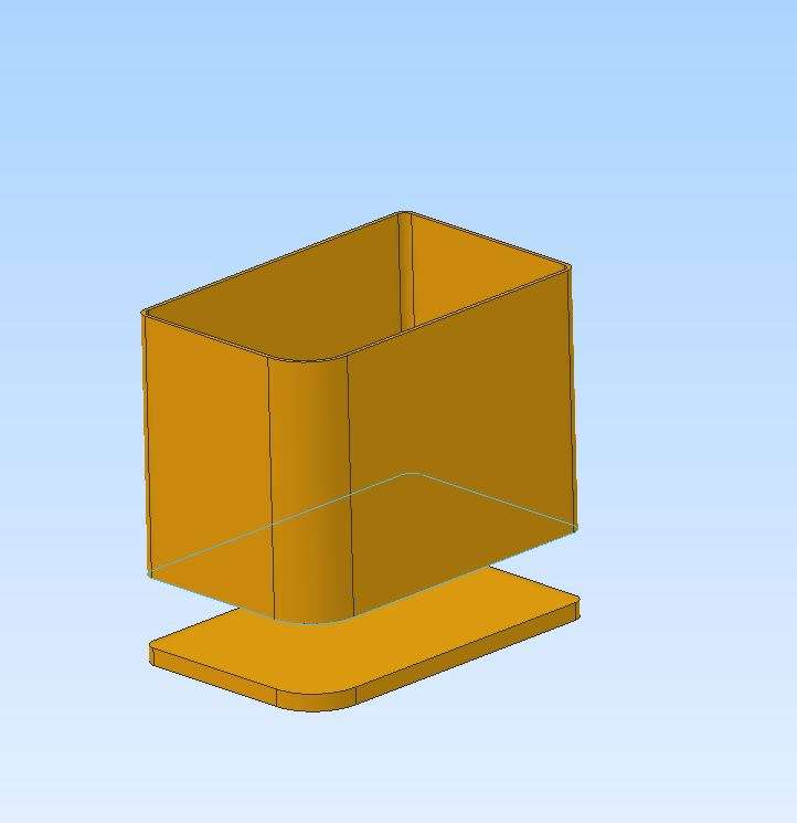
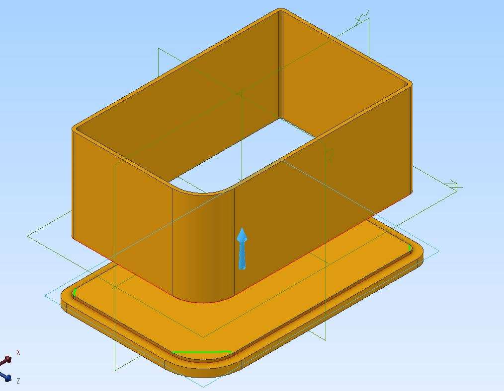
Making a rectangular box shape
Making a rectangular box shape
- This topic has 16 replies, 6 voices, and was last updated 12 March 2026 at 08:55 by
 JasonB.
- Please log in to reply to this topic. Registering is free and easy using the links on the menu at the top of this page.
Latest Replies
-
- Topic
- Voices
- Last Post
-
-
4¾” 13swg copper tubing?
Started by:
martynt50
in: Materials
- 1
-
2 August 2026 at 13:41
martynt50
-
can anyone make me a file? 3d file
Started by:
Ian Parkin
in: 3D Printers and 3D Printing
- 4
-
2 August 2026 at 13:34
Ian Parkin
-
newbie, with some initial questions about this forum
Started by:
frippy
in: General Questions
- 4
-
2 August 2026 at 13:31
Roderick Jenkins
-
Home thoughts from abroad
Started by:
martynt50
in: Introduce Yourself – New members start here!
- 4
-
2 August 2026 at 13:20
martynt50
-
Bleedin’ hydraulics!
Started by:
Kiwi Bloke
in: General Questions
- 9
-
2 August 2026 at 13:12
noel shelley
-
Why righthand threads?
1
2
3
Started by:
vintagengineer
in: General Questions
- 30
-
2 August 2026 at 13:08
bernard towers
-
Steam pressure guages
Started by:
Peter Venn
in: General Questions
- 7
-
2 August 2026 at 13:05
Martin Johnson 1
-
Lightning
1
2
3
Started by:
duncan webster 1
in: Electronics in the Workshop
- 17
-
2 August 2026 at 12:43
Robert Atkinson 2
-
Another new member in France
Started by:
jimalm
in: Introduce Yourself – New members start here!
- 8
-
2 August 2026 at 10:49
Russell Eberhardt
-
Myford S7 oil useage
Started by:
AStroud
in: Workshop Tools and Tooling
- 5
-
2 August 2026 at 10:38
JohnF
-
My adventures with a bench top CNC mill
1
2
3
Started by:
John Hinkley
in: CNC machines, Home builds, Conversions, ELS, automation, software, etc tools
- 8
-
2 August 2026 at 10:33
John Hinkley
-
The tea room
Started by:
larry phelan 1
in: General Questions
- 1
-
2 August 2026 at 10:20
larry phelan 1
-
Mystery debris?
Started by:
Bo’sun
in: The Tea Room
- 10
-
2 August 2026 at 09:50
Michael Gilligan
-
Decided to use castings
Started by:
BOB BLACKSHAW 1
in: General Questions
- 8
-
1 August 2026 at 21:56
Nigel Graham 2
-
My week this week! My workshop videos
1
2
…
13
14
Started by:
Phil Whitley
in: The Tea Room
- 16
-
1 August 2026 at 16:04
Phil Whitley
-
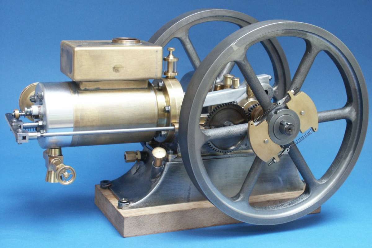
Vickers Inverted Engine
1
2
3
Started by:
JasonB
in: Stationary engines
- 13
-
1 August 2026 at 13:26
JasonB
-
Deep drilling
1
2
Started by:
Speedy Builder5
in: Workshop Techniques
- 14
-
1 August 2026 at 13:22
bernard towers
-
Marion Parker – R I P.
Started by:
Howard Lewis
in: The Tea Room
- 1
-
1 August 2026 at 12:51
Howard Lewis
-
Apple at its best
Started by:
Michael Gilligan
in: Electronics in the Workshop
- 5
-
1 August 2026 at 12:28
paul rayner
-
Marv Klotz Calculators for Model Engineers
Started by:
David Banham 1
in: Workshop Techniques
- 5
-
1 August 2026 at 10:51
Mark Rand
-
VFD querie
Started by:
tatler
in: CNC machines, Home builds, Conversions, ELS, automation, software, etc tools
- 3
-
1 August 2026 at 07:16
DC31k
-
Drill chuck manufacturer’s coding
Started by:
Bill Phinn
in: Workshop Tools and Tooling
- 5
-
31 July 2026 at 19:25
Bill Phinn
-
Trying to get my enthusiasm back
Started by:
BOB BLACKSHAW 1
in: General Questions
- 2
-
31 July 2026 at 16:08
BOB BLACKSHAW 1
-
Model Engineer and Engineering In Miniature
Started by:
Meridienne Exhibitions 1
in: Books
- 1
-
31 July 2026 at 13:45
Meridienne Exhibitions 1
-
blackgates eng
1
2
Started by:
Peter Daw
in: Beginners questions
- 22
-
31 July 2026 at 13:32
Trevor Drabble 1
-
4¾” 13swg copper tubing?


