
5″ loco support jig

5″ loco support jig

Home › Forums › General Questions › 5″ loco support jig

Viewing 21 posts - 1 through 21 (of 21 total)
  • Author
    Posts
  • #871464
    Peter Venn
    Participant
      @petervenn53369

      I am building Don Young’s 0-4-4 O2 and I’ve got to the stage now where the locomotive is on the home straight and therefore very heavy, but requires tipping in all directions to access different parts. Does anybody know of the availability of any frames to mount a locomotive such that it can be turned upside down, sideways etc. without having to design one and make it myself?

      I can’t believe that something is not commercially available because there must be quite a lot of demand.

      Thanks for any help in anticipation,

      Peter Venn

      #871469
      noel shelley
      Participant
        @noelshelley55608

        I’m not aware of such a thing. The variations in size from a simple 0-4-0 to a 2-10-0 mean that if it’s universal it will be big, heavy and very expensive. Your best to design and build something that suits your needs. Noel.

        #871475
        Nigel Bennett
        Participant
          @nigelbennett69913

          My late and much-missed friend Colin Abrey published a design for one in ME 4253 (05 Aug 2005). It gives you an idea of how one might look – and it is not a difficult thing to make if you’ve built a Fishbourne!

          #871494
          Bazyle
          Participant
            @bazyle

            There is a commercial offering called “Dexion” 🙂

            #871528
            Paul Lousick
            Participant
              @paullousick59116

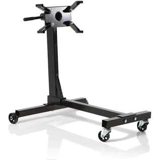
              Stands are available for repairing car engines that rotate thru 360 degrees. A special support jig would have to be made for attaching your engine. Car engines are attached to the stand by the flywheel mounting bolts.

              Engine stand

              #871552
              Speedy Builder5
              Participant
                @speedybuilder5

                Not quite so big as yours, but this is a simple support for my 0-6-0 SPEEDY.  I couldn’t balance the weight of the loco without external weights, so when you rotate the loco in the frame, it is has to be done with care.  The C of G alters as the model progresses.  My frame can be locked in any of the 4 quadrants ( 0deg, 90,180 etc).

                Bob

                UndercarriageView Large

                #871566
                noel shelley
                Participant
                  @noelshelley55608

                  Hey Bob that’s a neat and simple way to do it. The idea of hanging a possibly large model by just the front end, or back on a commercial engine building stand would worry me. The C of G will usually be above the buffer beam so one needs to be aware of this and account for it when rolling the locomotive over. Noel.

                  #871598
                  Peter Venn
                  Participant
                    @petervenn53369

                    Thank you to everybody who has contributed and the information has been very useful. I will be building my own frame I think and it will give me a chance to practice my rather rudimentary welding skills!

                    Maybe I should go into commercial production with something because it seems to be one of those things that everybody needs.


                    Peter Venn


                    #871602
                    JA
                    Participant
                      @ja

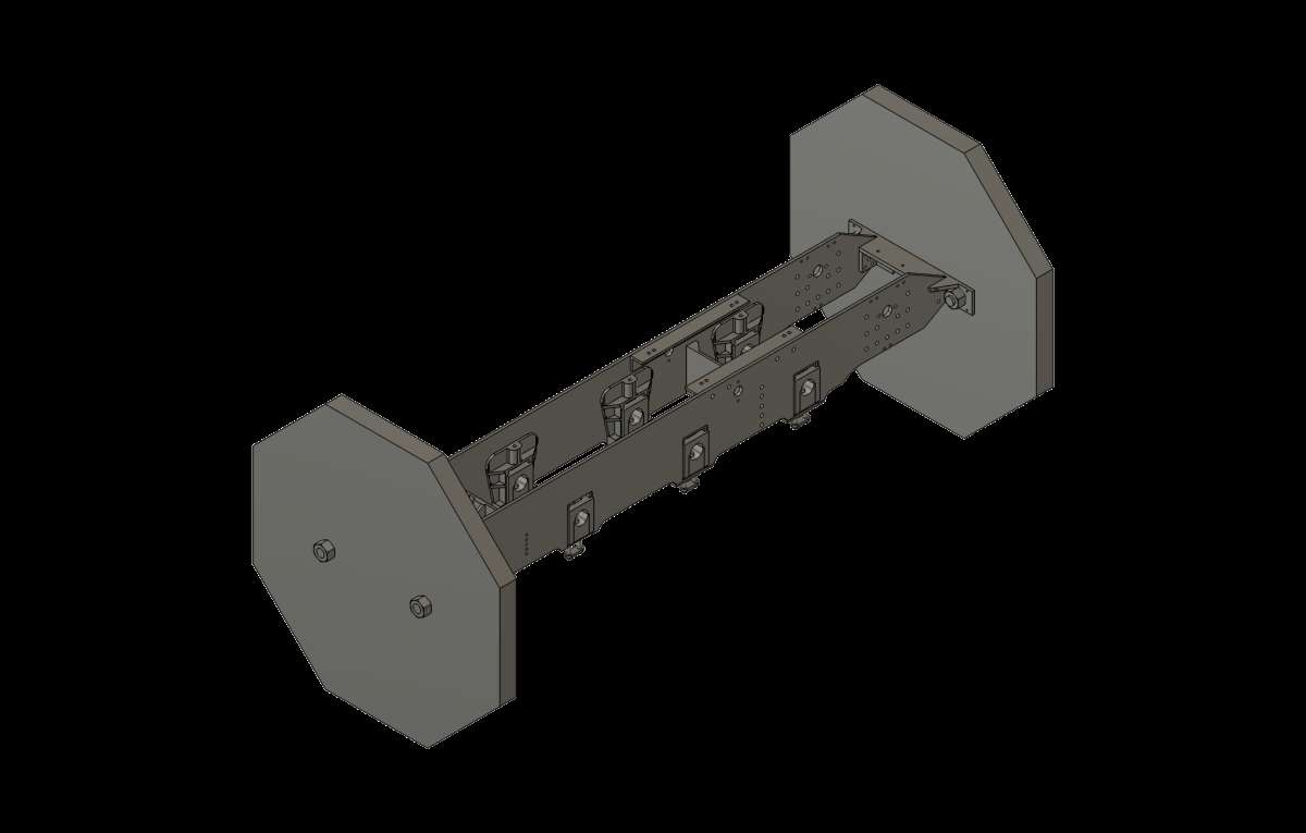
                      This is a simple turn-over jig that has been used by my club members. The person who introduced it found the design in a magazine. I have yet to cut the plywood so I have rapidly solid modelled the arrangement.


                      Turn-over stand v7


                      All it is is an octagonal 20mm or 25mm plywood disc bolted to each buffer beam. A 5″ gauge loco would need 15″ across the flats discs (sorry for the mixed units). Once in place the loco can be rolled over on the work bench. The shift in centre of mass when the boiler etc is erected can be accommodated by drilling more holes in the discs.

                      JA


                      #871621
                      noel shelley
                      Participant
                        @noelshelley55608

                        For those who can re purpose – a worm drive gear box say 25/1 ration, possibly a Croft box makes a perfect way to rotate a locomotive under control without the risk of it running away. Noel.

                        #871681
                        Nigel Graham 2
                        Participant
                          @nigelgraham2

                          Noel-

                          The car-engine stand should take the weight of a model locomotive but the locomotive will not take being cantilevered from just one end. Structurally, a car engine is a massive, rigid box so will cope with such treatment.

                          One potential answer, at some cost of accessibility, is to fit the stand with strongly-braced cantilever brackets whose outer ends are equipped to hold the respective buffer-beam

                          The worm-drive as you suggest is the ideal way to control a rotating stand and I think many such stands with worm-gears have been built. The ratio is not very important, but should be reasonably high.


                          JA –

                          My own club still has the thick plywood end-plates for just such a roll-over stand, made for a 7¼” g. tank-loco I think.

                          I don’t know when it was made, nor whether it was inspired by a published example as yours was, or the brain-child of one of our members

                          However I would suggest giving it longitudinal tie-rods – M16 or M19 studding on ours I think – linking the apices to resist any tendency for the discs to rotate relatively to each other or out of parallel, and twist the engine chassis.

                          The loco frame will try to act as a tie, but it is not designed for such an unfair load.

                          #871686
                          Paul Lousick
                          Participant
                            @paullousick59116

                            Noel, I was thinking of a cradle of some sorts, attached to the engine stand to hold the locomotive.

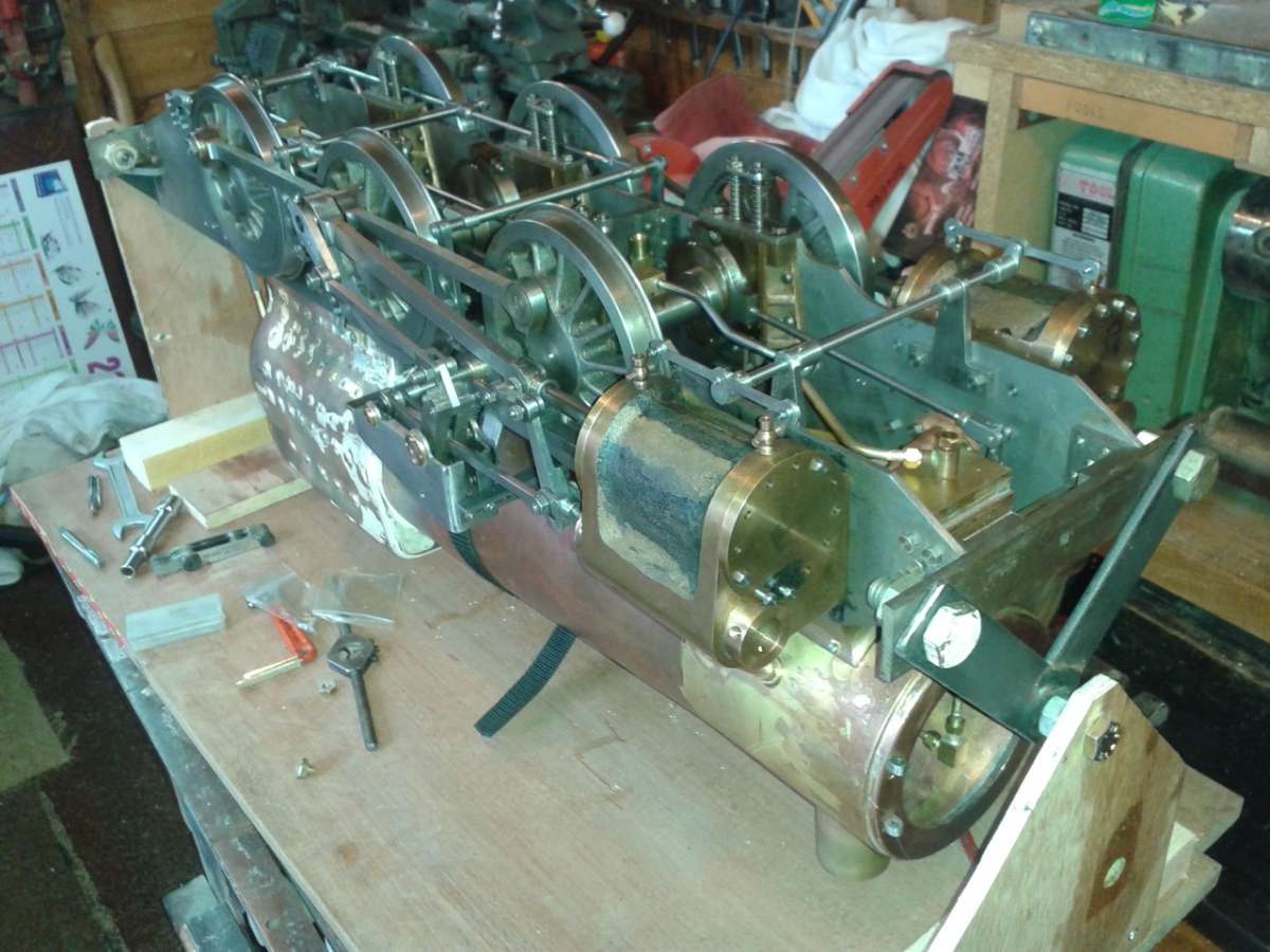
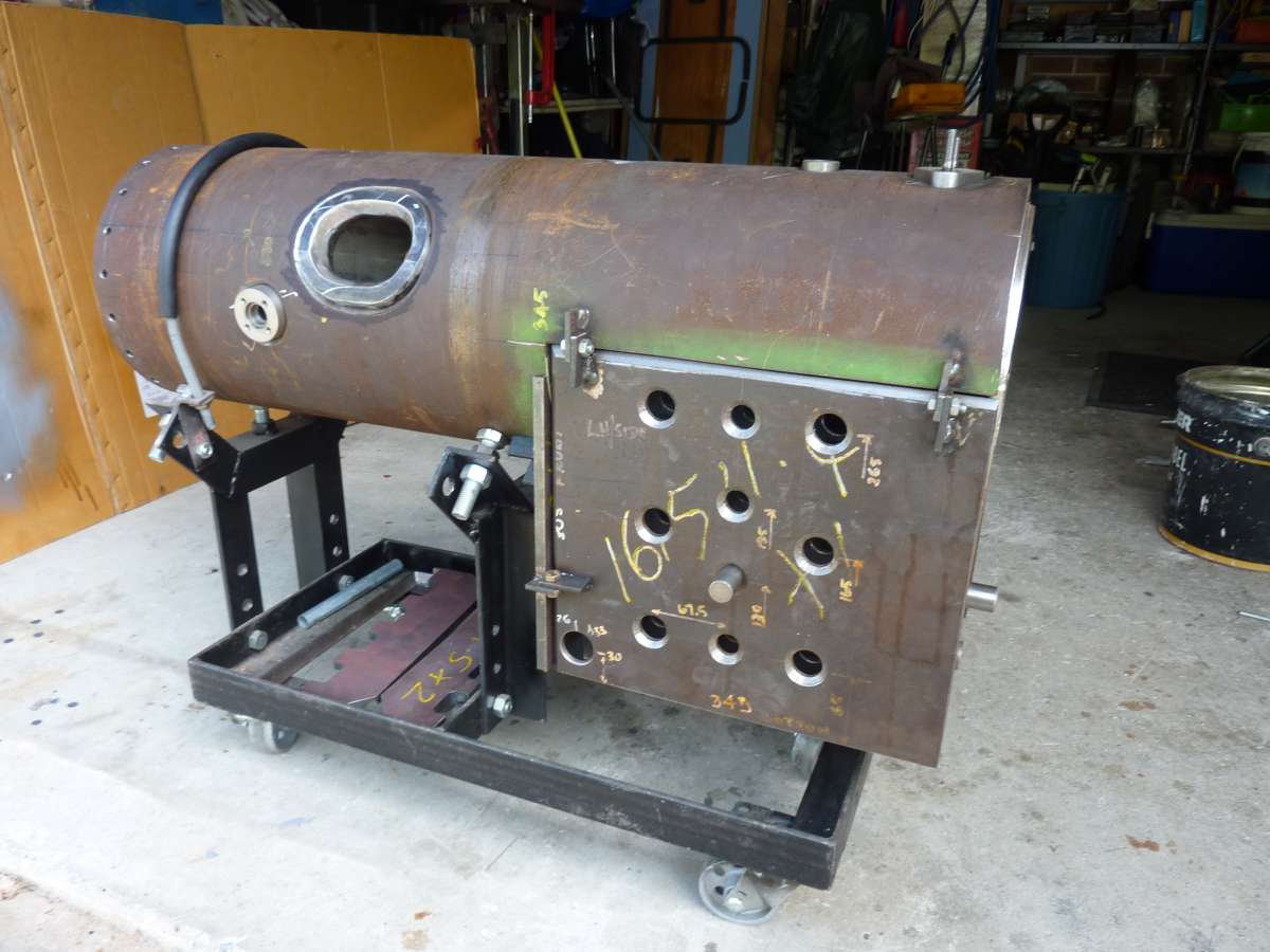
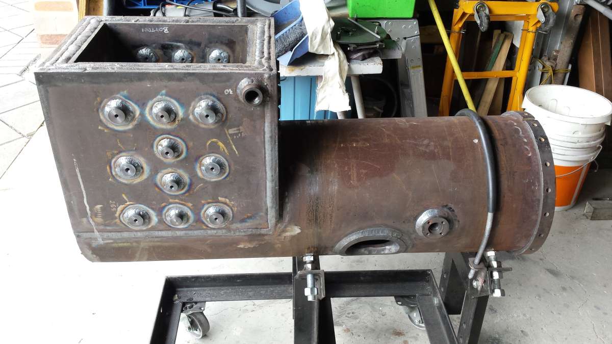
                            On a side note. this is the stand that I use to fabricate the boiler for my 6″ traction engine.  The tube is 273mm OD x 10mm thick

                            Boiler Stand Boiler stand 2

                            #871700
                            Speedy Builder5
                            Participant
                              @speedybuilder5

                              The plywood “wheel” idea is simple, but needs a nice wide bench when rolling the loco over. Once the loco is fully constructed, I did wonder as to wether the cast iron buffers were strong enough to bear the weight of the loco – its the same problem that I have with my support frame.

                              Bob

                              #872037
                              howardb
                              Participant
                                @howardb
                                On Paul Lousick Said:

                                Stands are available for repairing car engines that rotate thru 360 degrees. A special support jig would have to be made for attaching your engine. Car engines are attached to the stand by the flywheel mounting bolts.

                                Engine stand

                                I used a similar engine stand for ten years + in my engine and transmission business, it was mostly used to mount small block 350 cu inch – 5.7 litre GM V8’s for repair/rebuild on it.

                                The engines were mounted using the flywheel housing bolts, it looks dreadfully insecure but never had one come off, they do get a bit top heavy so watch that.

                                From memory I bought it from Machine Mart.

                                https://www.machinemart.co.uk/p/clarke-ces450-450kg-engine-stand/

                                #872072
                                noel shelley
                                Participant
                                  @noelshelley55608

                                  The engine stand idea is a good basis but would require some sound engineering to arrange a support at the other end adjustable for length with a plumber block or some form of bearing to allow rotation in the horizontal axis. The only snag with the engine stand is having a workshop big enough to be able to move it about. For those with welding and fabrication skills and gear, a frame made of 25mm box 2mm wall with a pair of plumber blocks will work and can sit on a bench. Being able to make an adaptor plate to bring the C/G in line with the bearing centreline will allow easy rotation and avoid the risk with a heavy loco that it roll over uncontrolably – hence the use of a worm drive box if possible. 3.5″ G is one thing, 5″G could weight 100Kg or more and 7.25″ G is another level, 500Kg +  Noel.

                                  #872120
                                  Howard Lewis
                                  Participant
                                    @howardlewis46836

                                    +1 for those suggesting support at both ends.

                                    For large I C engines, both ends are supported, you wouldn’t support a 16 litre engine just at one end!. Car engines, smaller ones, can be supported by the side mountings.

                                    A loco,  in 5″ gauge will be too much for one person to lift safely, and supporting at just one end could lead to distortion.

                                    So, support at both ends; and since the C of G will move, and the weight increase, as the model progresses.

                                    To rotate the frame, using a single start worm, and wheel will make it safe from running away.

                                    Howard

                                    #872148
                                    martin haysom
                                    Participant
                                      @martinhaysom48469
                                      On Howard Lewis Said:


                                      To rotate the frame, using a single start worm, and wheel will make it safe from running away.

                                      Howard

                                      or you could just use a longer lever

                                      #872158
                                      noel shelley
                                      Participant
                                        @noelshelley55608

                                        Let the lever  go and gravity takes over ?

                                        #872164
                                        duncan webster 1
                                        Participant
                                          @duncanwebster1

                                          And? It swings. I’ve built 3 locos on a simple stand without a worm drive, still got all my fingers

                                          #872174
                                          Speedy Builder5
                                          Participant
                                            @speedybuilder5

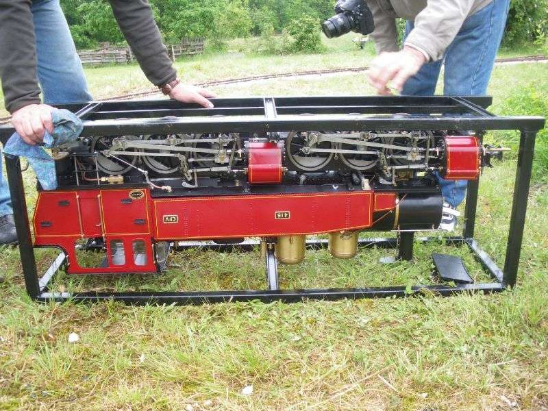
                                            I made a transporting frame similar to this 5″ loco. You can see it’s ideal for sorting out problems at the track side. Remember to empty the reservoir for the steam oil first !!

                                            locoSupport Rig

                                            #872206
                                            Bill Dawes
                                            Participant
                                              @billdawes

                                              I made a simple cradle for my Emma Victoria, agreed a relatively light 0-4-0 loco.

                                              I took the buffers out, a crossbar at each end drilled for the buffer housings supported the loco.

                                              The crossbar at each end had a bolt through them into an upright and acted as a pivot.

                                              A pin through one end kept it in position.

                                              All very simple, about an hours work and made from scrap timber.

                                              Bill D.


                                            Viewing 21 posts - 1 through 21 (of 21 total)
                                            • Please log in to reply to this topic. Registering is free and easy using the links on the menu at the top of this page.

                                            Latest Replies

                                            Home › Forums › General Questions › Topics

                                            Viewing 25 topics - 1 through 25 (of 25 total)
                                            Viewing 25 topics - 1 through 25 (of 25 total)

                                            View full reply list.