DC motor + speed controller

DC motor + speed controller

Home Forums General Questions DC motor + speed controller

Viewing 20 posts - 1 through 20 (of 20 total)
  • Author
    Posts
  • #228982
    MW
    Participant
      @mw27036

      Hi,

      I'm interested in making a DC motorized control for my lathe lead screw and i know there are lots of designs out there but i dont really know where to start with regards to where to buy a DC motor and what size/speed would be appropriate to drive a handle?

      Michael W

      #24430
      MW
      Participant
        @mw27036
        #228983
        John Rudd
        Participant
          @johnrudd16576

          Ex- car wiper motor and the speed controller featured in MEW?

          #228984
          Michael Cox 1
          Participant
            @michaelcox1

            If you put 12 volt dc motor into ebay you will get many hits. Most of the 35 mm diameter motors will have sufficient power to drive the leadscrew of a small minilathe. I have fitted a motorised leadscrew to my lathe, see:

            http://mikesworkshop.weebly.com/leadscrew-motor.html

            http://mikesworkshop.weebly.com/new-threading-banjo.html

            http://mikesworkshop.weebly.com/control-circuits.html

            Mike

            #228987
            Les Jones 1
            Participant
              @lesjones1

              I would suggest starting by measuring the maximum torque required to turn the leadscrew at the tightest point in the travel.(Use a spring balance and string wrapped round the handwheel.) I would then choose a motor rated with at least twice that torque rating. You also need to decide what the maximum speed is that you want to turn the leadscrew. When you have found a suitable motor you can start designing the drive electronic to match the motor voltage and current rating. You will also then need to decide how well you want the speed controlled. If you do not require accurate speed control the just a PWM controller will do. If you want accurate speed control you will need a closed loop system with some form of tacho generator or encoder for feedback.

              Les.

              #228996
              MW
              Participant
                @mw27036

                Hi everyone, i'll try to address everyone.

                Hi john, Yes i do have that article in the well thumbed issue somewhere, I'm sure alot of these designs require a proper PCB board, i dont have the time/equipment/knowledge to make one of these, so i'd either have to get someone else to make it or use breadboards/wires to link up all the components.

                Thanks for the Reply mike, i think i'll try the 35mm spindle size then, as in my mind, for a task this small i dont have any concept of power or appropriate speeds so i just needed a starting point or rough guide. I keep looking at your website and i can really tell you have a background in electronics because of how well you've integrated the whole system. I will keep reading it for hints, thankyou.

                Les, i was thinking along the route of using pulleys/timing belt with a tensioning idler spindle, a bit more common and easier than an encoder to do. I lost my spring balance a long time ago!

                Thankyou,

                Michael W

                #229002
                John Haine
                Participant
                  @johnhaine32865

                  Maplin sell a speed controller…

                  **LINK**

                  Not worth building one at this price.

                  #229008
                  Tim Stevens
                  Participant
                    @timstevens64731

                    Rather than measuring the torque required and using that (doubled) to choose a motor, I suggest you look at a reduction by belt drive. This can be round or toothed, and it will allow you to select a motor which has less torque and more speed (ie most motors) than you actually need. A five times speed reduction will give you five times the motor torque, and one fifth of the speed. The drive etc needs to have a fail-safe built in, perhaps relying on a round belt will do, to avoid any possibility of driving the saddle through the headstock. Microswitches are helpful here, and perhaps a fuse to blow just below the stalled current to avoid burn out.

                    I have done this on the leadscrew (effectively) of a mill, and if you need details of motor etc I will pull it down off the shelf and peer at it for you. Just say.

                    Regards, tim

                    #229009
                    Neil Wyatt
                    Moderator
                      @neilwyatt

                      If you want to consider a stepper drive one that will allow you to do things like threading with it, wait for the next MEW which will have an article that goes through installation of a kit-build system in detail.

                      Neil

                      #229016
                      Bob Brown 1
                      Participant
                        @bobbrown1

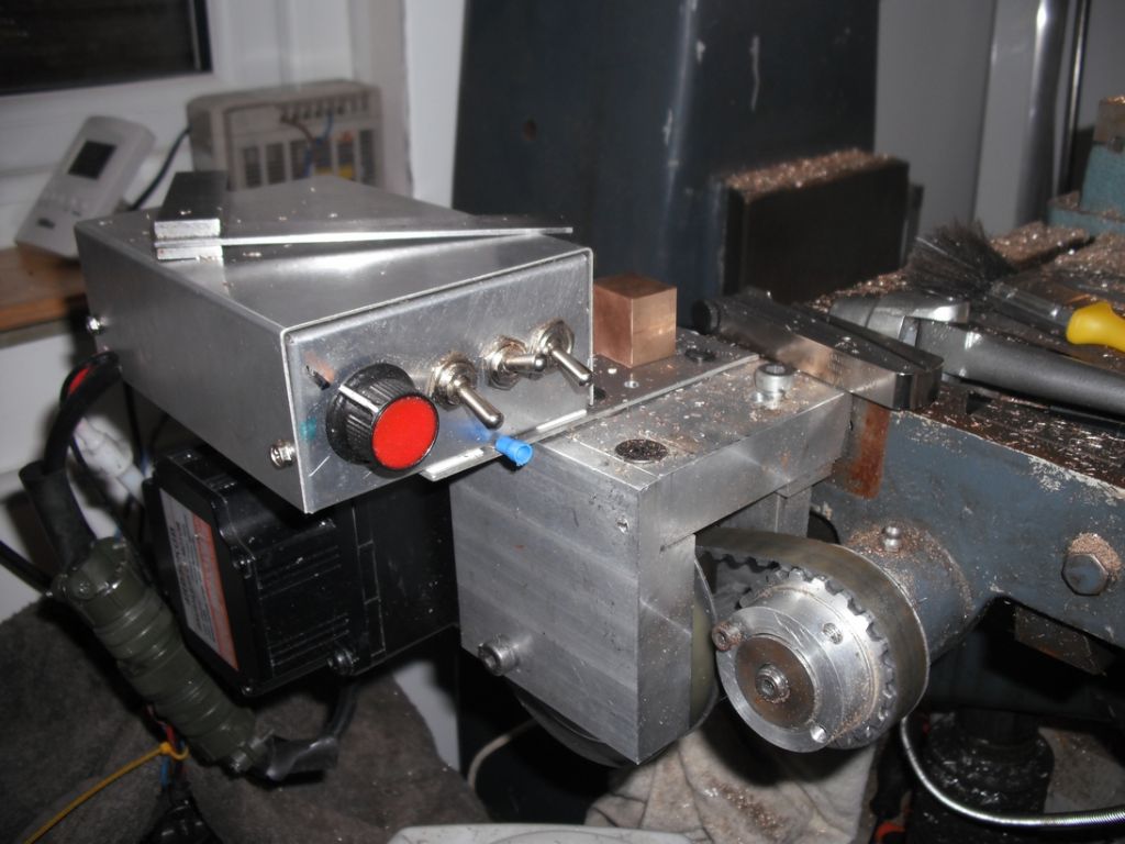
                        This is what I did on my milling machine using a BLDC geared motor

                        Bob

                        4.jpg

                        #229023
                        john fletcher 1
                        Participant
                          @johnfletcher1

                          I bought a DC motor speed controller it easily controls a 300 watt motor from PRC via ebay for £9.30. I couldn't buy the components for that price. I carefully removed the speed potentiometer, bought a new one and was able to mount it remote. Work well, with 6 mosfets and heat sink, pulse width modulation circuit. No feed back of course all in a smart box. John

                          #229208
                          MW
                          Participant
                            @mw27036

                            I just bought a mish-mash of components on ebay-

                            Motor 12v 38mm

                            **LINK**

                            12v Speed controller curcuit.

                            **LINK**

                            2amp 12v DC plug

                            **LINK**

                            x2 Pulleys

                            **LINK**

                            x2 Belts (same tooth pitch as pulley)

                            **LINK**

                            And finally x1 STDP switch (12v)

                            **LINK**

                            The fittings for installation can all be made to fit by me, so if you've taken the time to browse through that myriad, thanks and do you think that'll cut it? I always apprieciate the honesty of this forum so your opinion will count, I can always make changes to this list because its all on china post and it'll take forever anyway, there will be plenty of time to change my mind if needed.

                            Michael W

                            #229211
                            Ajohnw
                            Participant
                              @ajohnw51620

                              You need to work out what rev range you need. Think in terms of thou's per rev. I just did that for a table feed on my miller. Ideally I need a range from 2.5 to 80rpm acounting for the speeds the cutter will run at. There is a point between the 2 and the 5. Rather wide without a gearbox. This means that a stepper might be a better option. One with a gear head to get the torque up.

                              John

                              #229217
                              John Haine
                              Participant
                                @johnhaine32865

                                One way to think about it is that a lathe normally has only one or two power feed speeds, so perhaps you don't need the range that you'd like on a mill. Perhaps start with the normal max speed on the lathe auto-act, bear in mind that the slowest one is too fast for some things, so go from perhaps 1/3 of the slowest to 2x the fastest, and you should have something a lot more versatile than the mechanical feed.

                                That speed controller only gives a 10:1 range of PWM ratios so may be a bit limited depending on the above calculation.

                                The motor looks a bit tiddley to me, I'd go for something beefier. Also I think 2A is light for the PSU – just been reading Mike Stratton's article on power drawbar in the latest MEW, he got a 25 amp 12 V PSU for £17 off eBay. It's always useful to have lots of amps round the workshop.

                                Final point, some speed controllers don't like having their outputs open circuited when you throw a reversing switch when the motor is running, a centre-off switch might be useful so the motor can stop before the reverse volts are applied.

                                Edited By John Haine on 09/03/2016 17:23:24

                                #229220
                                MW
                                Participant
                                  @mw27036

                                  I need it to be slow enough to get a good finish but also fast enough to move about with ease. The main bonus of it is the ability to get a nice consistent turned finish which is the hallmark of any precision cylinders.

                                  The motor is fairly small, i would say roughly hand sized motor, which is just enough. The idea of me playing around with any sort of power above a 13A socket makes my spine tingle a bit. If i deemed it truly necessary, i wouldnt want to do that without a qualified electrician present. I deliberately sized my own machine motors to fit within 13A for that very reason.

                                  I don't plan on reversing it, although that may seem a bit lame, i don't know how i would switch the tracks to make it reverse to be honest.

                                  Michael W

                                  #229224
                                  Ajohnw
                                  Participant
                                    @ajohnw51620

                                    The 2 normal feeds on the lathe always relate to speed John – that's the catch. They are per rev what ever the speed the lathe is running at.

                                    It's a natural for a geared down stepper really as the revs are so slow angel 2 but I really don't fancy writing any software and if some one did it would probably have a display and scrolling buttons etc.

                                    John

                                    #410927
                                    Tony Pratt 1
                                    Participant
                                      @tonypratt1
                                      Posted by Neil Wyatt on 08/03/2016 14:41:14:

                                      If you want to consider a stepper drive one that will allow you to do things like threading with it, wait for the next MEW which will have an article that goes through installation of a kit-build system in detail.

                                      Neil

                                      Hi,

                                      I can't locate the article that Neil mentions above, can someone please point me in the right direction?

                                      Thanks,

                                      Tony

                                      #410936
                                      clivel
                                      Participant
                                        @clivel
                                        Posted by Tony Pratt 1 on 25/05/2019 16:43:28:Hi,

                                        I can't locate the article that Neil mentions above, can someone please point me in the right direction?

                                        Thanks,

                                        Tony

                                        I think the article he is referring to is in MEW #240, April 2016. Building an electronic leadscrew – Chris Gabel converts his lathe using the electronics kit from Automation Artisans.

                                        Clive

                                        #410937
                                        Tony Pratt 1
                                        Participant
                                          @tonypratt1

                                          Thanks Clive I will investigate!

                                          Tony

                                          #410955
                                          Andy Carruthers
                                          Participant
                                            @andycarruthers33275

                                            Check out YouTube – Clough42 – developing an electronic lead screw

                                          Viewing 20 posts - 1 through 20 (of 20 total)
                                          • Please log in to reply to this topic. Registering is free and easy using the links on the menu at the top of this page.

                                          Latest Replies

                                          Home Forums General Questions Topics

                                          Viewing 25 topics - 1 through 25 (of 25 total)
                                          Viewing 25 topics - 1 through 25 (of 25 total)

                                          View full reply list.