How to bore headstock bearing housings?
How to bore headstock bearing housings?
- This topic has 11 replies, 7 voices, and was last updated 2 May 2017 at 11:16 by
 Hopper.
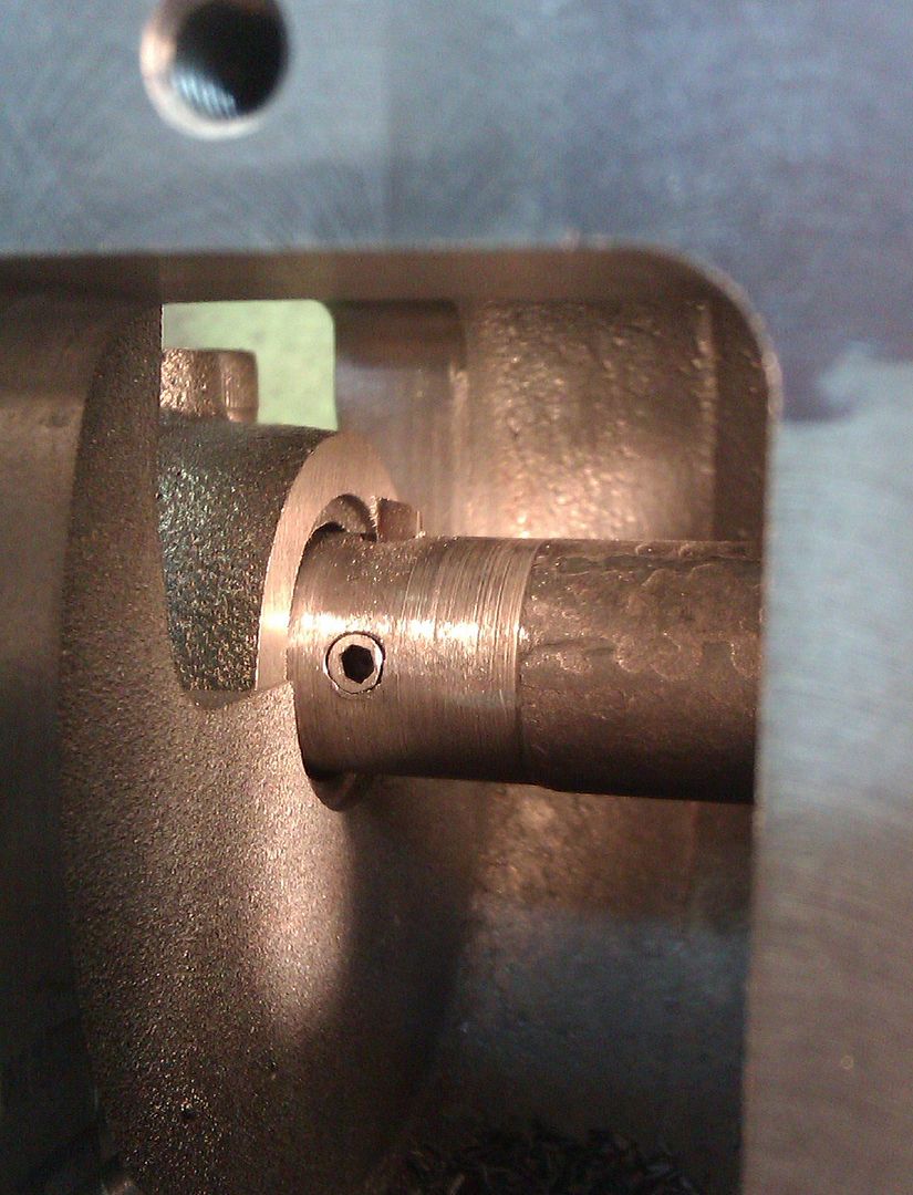
![img_20170501_145643[1].jpg](/wp-content/uploads/sites/4/images/member_albums/141632/739352.jpg "img_20170501_145643[1].jpg")
![img_20170501_145655[1].jpg](/wp-content/uploads/sites/4/images/member_albums/141632/739353.jpg "img_20170501_145655[1].jpg")


- Please log in to reply to this topic. Registering is free and easy using the links on the menu at the top of this page.
Latest Replies
-
- Topic
- Voices
- Last Post
-
-
Hot milk variations
Started by:
Gary Wooding
in: The Tea Room
- 1
-
24 June 2026 at 10:33
Gary Wooding
-
Running 380V 3-phase motor on 230V 1-phase
1
2
Started by:
jimalm
in: Electronics in the Workshop
- 14
-
24 June 2026 at 09:57
Bob Worsley
-
Hot radiators in summer
Started by:
Gary Wooding
in: The Tea Room
- 8
-
24 June 2026 at 09:17
Gary Wooding
-
Letters and Parcels Box
Started by:
Michael Gilligan
in: The Tea Room
- 1
-
24 June 2026 at 09:05
Michael Gilligan
-
Rapidor 3XM
Started by:
homecat88
in: Introduce Yourself – New members start here!
- 2
-
24 June 2026 at 08:13
homecat88
-
digital microscope for poor eyesight
Started by:
bernard towers
in: Electronics in the Workshop
- 11
-
24 June 2026 at 07:35
bernard towers
-
Testing Single Point Thread Fitment
Started by:
berwick
in: Beginners questions
- 13
-
24 June 2026 at 05:19
Diogenes
-
Gas Tap Valves. Vintage
1
2
3
Started by:
dee
in: Related Hobbies including Vehicle Restoration
- 19
-
23 June 2026 at 21:24
Nigel Graham 2
-
Taylor Hobson Pantograph Engraver Model D
1
2
Started by:
jaCK Hobson
in: Workshop Tools and Tooling
- 10
-
23 June 2026 at 21:05
Charles Jambon
-
Model Turbines
1
2
…
26
27
Started by:
Turbine Guy
in: Stationary engines
- 28
-
23 June 2026 at 20:21
Turbine Guy
-
Rapidor Manchester re-build
Started by:
homecat88
in: Introduce Yourself – New members start here!
- 3
-
23 June 2026 at 19:19
homecat88
-
Advice required
Started by:
janet.ho001
in: Introduce Yourself – New members start here!
- 4
-
23 June 2026 at 19:12
janet.ho001
-
Orbital – Not your Usual Oscillator!
1
2
Started by:
JasonB
in: Stationary engines
- 14
-
23 June 2026 at 19:11
JasonB
-
Clarkson Horizontal – Redefined in Metric
Started by:
JasonB
in: Stationary engines
- 8
-
23 June 2026 at 18:48
JasonB
-
3D Printing in the Home Workshop
Started by:
Colin Heseltine
in: 3D Printers and 3D Printing
- 3
-
23 June 2026 at 17:01
Fulmen
-
Rob Roy Build
Started by:
Dalboy
in: Locomotives
- 4
-
22 June 2026 at 21:24
Dalboy
-
Help identifying a mystery thread
Started by:
Beardy Mike
in: Beginners questions
- 8
-
22 June 2026 at 19:04
Nicholas Farr
-
Unwanted Car Software Update
Started by:
Chris Crew
in: The Tea Room
- 12
-
22 June 2026 at 16:48
paul1956
-
Oiling Lathe Ways
Started by:
Blue Heeler
in: Beginners questions
- 7
-
22 June 2026 at 13:34
Bazyle
-
Farm Boy dimensions
Started by:
Speedy Builder5
in: Stationary engines
- 3
-
22 June 2026 at 13:02
JasonB
-
Nickel Silver
Started by:
Carl
in: Materials
- 10
-
22 June 2026 at 11:52
Roderick Jenkins
-
Flame Licker Engine & USA made 1930’s Empire Water Pump
Started by:
Blue Heeler
in: Miscellaneous models
- 2
-
22 June 2026 at 10:03
Bazyle
-
Film Projectors/Astronomy/Radio Ham-Mark Stuckey
Started by:
Mark Easingwood
in: Related Hobbies including Vehicle Restoration
- 1
-
21 June 2026 at 22:40
Mark Easingwood
-
Baffled by flatted-shank spot weld drills
Started by:
Bill Phinn
in: Workshop Tools and Tooling
- 4
-
21 June 2026 at 22:26
Bill Phinn
-
Wallace valvegear simulator
1
2
Started by:
Kevan Shaw
in: General Questions
- 7
-
21 June 2026 at 21:32
Kevan Shaw
-
Hot milk variations


