Turning wheel flange taper on a myford ml7

Advert

Turning wheel flange taper on a myford ml7

Home Forums Workshop Techniques Turning wheel flange taper on a myford ml7

Viewing 16 posts - 1 through 16 (of 16 total)
  • Author
    Posts
  • #724688
    Hobbs
    Participant
      @edwardhobbs3

      Hallo folks,

      It’s a year later and I’m finally getting around to completing the wheels for my Shay project, but I appear to have run into an issue.

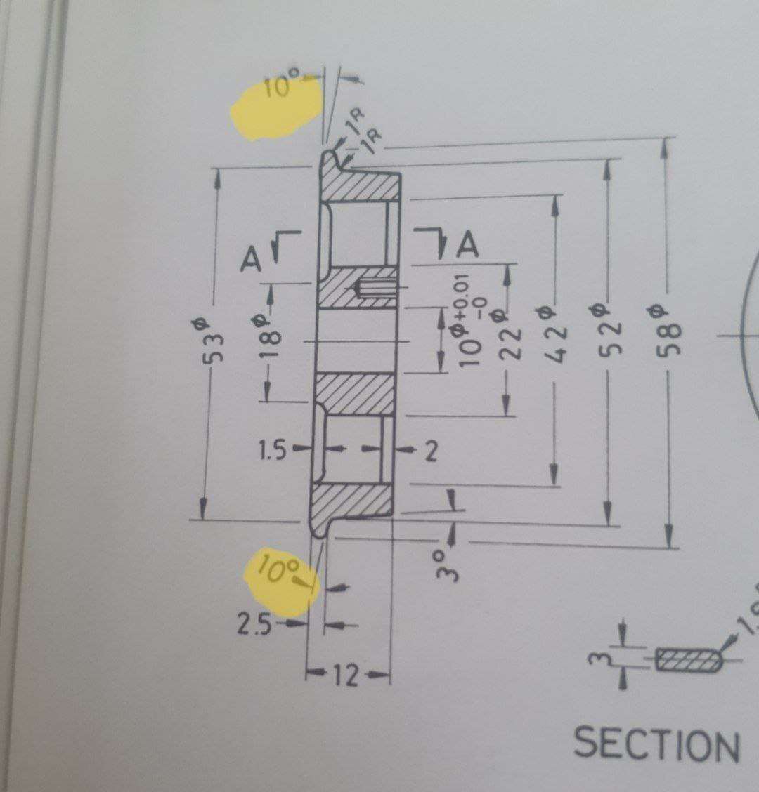
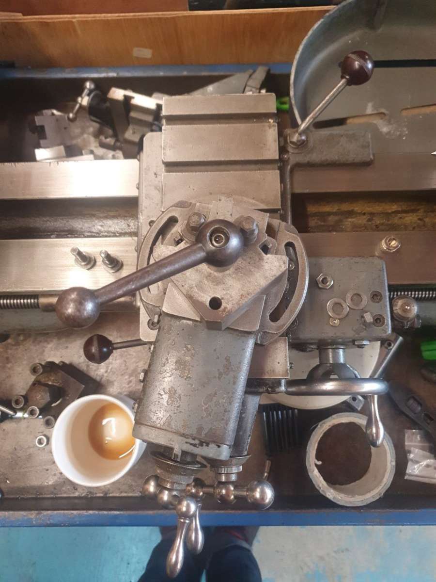
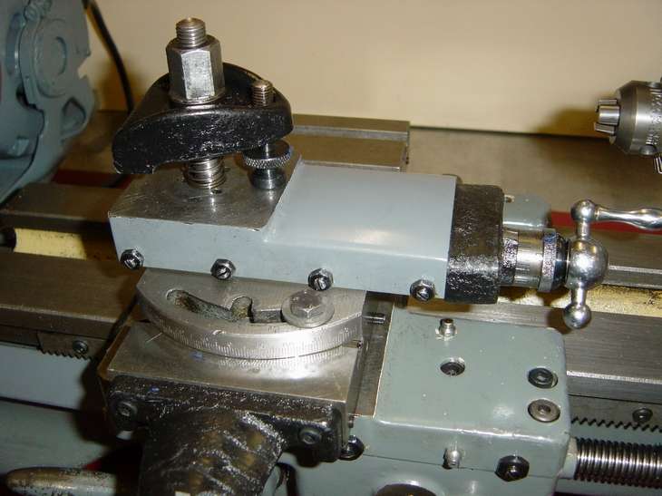
      I’ve completed every feature other than the taper on the flanges – the drawing says these should be 10*. However, I don’t appear to be able to arrange the compound to actually cut such an angle. Anything past ~45 degrees or so and the clamping slots “fall off” and there’s no way to secure it.

      I’m sure I’m missing something obvious as i’m not the first person to make locomotive wheels on a myford, maybe I need to make a forming tool with the correct angle built in?

      Any advice would be greatly appreciated.

      wheel drawingcross slide

      Advert
      #724693
      Speedy Builder5
      Participant
        @speedybuilder5

        The chamfer is only 2.5mm wide, for the inside I would use a flat faced tool set at 10 degrees. Make sure your gibs are set tight to prevent chatter. Similar for the inside taper but have a 1R radius on the nose.

        #724706
        duncan webster 1
        Participant
          @duncanwebster1

          Tool with the correct nose radius and the flank set at 10 degrees. I know it works for cast iron wheels on an ML7 because that’s how I did mine, and they had a bigger nose radius. Lock the saddle and make a note of the dial readings so they all come out the same. Not easy to measure the diameter on a taper.

          #724708
          duncan webster 1
          Participant
            @duncanwebster1
            • On duncan webster 1 Said:

              Tool with the correct nose radius and the flank set at 10 degrees. I know it works for cast iron wheels on an ML7 because that’s how I did mine, and they had a bigger nose radius. Lock the saddle and make a note of the dial readings so they all come out the same. Not easy to measure the diameter on a taper.

              The 10 degrees on the inside is not important.

            #724722
            Nigel Graham 2
            Participant
              @nigelgraham2

              I’ve just experimented with my ML7 to verify what it can and can’t do.

              Th tread angle is the important one, and consistency of taper and diameter is much more important than the angle value (within reason). The top-slide will handle that.

              For the flange, as others point out, simply use a form-tool.

              On a more general point when turning tapers and cones on an ML7, I’ve occasionally solved an awkward setting problem by using the tool upside down and cutting from behind the work (i.e. on the up-coming side).

              #724735
              bernard towers
              Participant
                @bernardtowers37738

                When I had a ML7 many moons ago the topslide had two further slots machined halfway along the long slots and were machined towards the slide (inwards) cant remember. why but might that help for setting other angles?.  Home and Workshop Machinery have got one like that for sale on the bay at the moment!!

                #725441
                Nigel Graham 2
                Participant
                  @nigelgraham2

                  Ah – my lathe does not have those but I have seen them elsewhere.

                  Do they allow the T-bolts to engage the slots in the cross-slide when the compound slide is turned through 90º?

                  If so I think they are for use with the Taper-turning Attachment, allowing the compound slide to be used directly for the depth of cut while the cross-slide is being driven by the attachment.

                  The cross-slide screw and nut are removed for taper-turning, with the secondary effect of allowing the top-slide to swing round without obstruction, but putting its quadrant slots off the edges of the cross-slide.

                  So those two branch-slots then allow the T-bolts to move inboard and enter the slide slots.

                  For lathes without those branch-slots the compound-slide is set at a steep angle but you may need account for the axial movement of the tool as well as its radial movement being less than what the dial reads.

                  #725675
                  bernard towers
                  Participant
                    @bernardtowers37738

                    Compound slide base on the bay at present with cut outs and good price!!!

                    #725784
                    Hopper
                    Participant
                      @hopper

                      Im not sure those cutouts on the curved slots on the late model topslides will allow you to rotate the topslide any further than the earlier plain curved slots. They might still be hanging out in mid air either side of the cross slide table? And there is no T slot in that central location in line with the pivot hole that those cutouts would align with?. I think those cutouts may be just so you put the T bolts in them when the topslide is in the standard 0 degree position (ie parallel to the lathe bed axis) to get them out of the way of some jobs and tooling. I’ll have to check it out next tiem I am in the shed.

                      There have been articles over the years in ME/W and some of the old boys’ books about making two little outriggers that attach to the sides of the cross slide with studs that stick up so you can rotate the topslide and clamp it down at either the 90 degree position for taper turning attachment use, or even to the 60 degrees (from lathe bed axis) position for screwcutting. Some of those “outriggers” attach via clamps in the cross slide T slots. Others may require some drilling and tapping of the sides of the cross slide. It’s one of those “worthwhile little projects” I have thought about making for years but never got around to it, as I leave the topslide where is for screwcutting and use the advance-it-by-half-of-cut-depth method.

                      slotted topslide

                      #725787
                      Martin Connelly
                      Participant
                        @martinconnelly55370

                        Can you make an intermediate plate of say 6mm/¼” steel to put between the compound and cross slide and lower the tool to suit? Alternatively can you clamp the compound to the T slot with machine tool style clamps?

                        Martin C

                        #725802
                        Nigel Graham 2
                        Participant
                          @nigelgraham2

                          Hopper –

                          A good point. When I replied previously I did not think to test if there are T-slots in line with the pivot.

                          The standard top-slide will rotate sufficiently for angled feeds in screw-cutting because you rotate it by half the thread’s included angle, and it would be a very odd thread indeed whose half-angle is >30º.

                          At 45º you are looking at the Buttress Thread, as that is the longer flank’s angle to the axis. Though it would not be easy, and cutting high-lead threads of any form is unkind to a Myford-sized lathe.

                          .

                          Martin –

                          You could make an adaptor-plate as you suggest, though 1/4″ is a significant loss of tool-setting height on a small lathe, and loses most of the pivot engagement. You also need consider if the slide will still rotate enough without its own hand-wheel and dial striking those of the cross-slide.

                          If the Tee-bolts need be outside of the cross-slide edges, or are replaced by studs, the plate could be reduced to 1/8″ but obviously still needs be flat on both faces. Gauge-plate may be a candidate. Another option is to machine a thicker mild-steel – or even aluminium-alloy – plate all over and bore a 1/8″ deep nest for the slide’s underside, including the flanges. This will also tend to stiffen it slightly.


                          Clamps? No. For a start there is nothing for the lower jaw to engage safely anyway.

                          Much more seriously, it would risk breaking the slide or Tee-slot flanges. They are castings designed to be compressed over their full areas to a machined surface, not loaded in cantilever form.

                          #725804
                          Tomfilery
                          Participant
                            @tomfilery

                            Hobbs,

                            I usually do mine with a triangular carbide insert – using it as a form tool.  Odd, isn’t it?  I usually do the other two tapers as a “properly turned” taper and do the rear taper with a form tool – the opposite of what others have told you (and which ignore the fact that you have to have the ability to grind the correct from tool for doing the flange and rim tapers in one go – perhaps they haven’t done railway wheels before)!

                            The carbide tools I use have one angle set at 25 degrees, so I only have to set the topside to 15 degrees to do the job – obviously, it depends on the geometry of your own tooling.

                            Regards Tom

                            #725807
                            Hobbs
                            Participant
                              @edwardhobbs3

                              Thanks everyone, super helpful.

                              I think Hopper is right in that the extra slots wouldn’t line up in a useful way, I can check when I’m in the workshop next week.

                              I think I’ll look at setting a flat tool to the right angle first and see how I get on, at the very least they’ll all be the same if not quite to the plans – at least the treads are correct.

                              The reason I wanted to use the myford for this was I have the fixture turned in place and set up already, but if I don’t have a suitable tool I have access to another lathe that does have a 360* compound and set up a new fixture (that lathe doesn’t currently have a 4-jaw or I’d have gone directly to that 😁)

                              #725809
                              duncan webster 1
                              Participant
                                @duncanwebster1

                                For angled in feed you rotate the top slide to (90-half thread angle), and ML7 won’t do it.

                                Without a tool post, the distance from top of topslide to centre is plenty to allow a 6mm plate twixt topslide and cross slide, although I never felt the need.


                                If you look at SMEE wheel standards they don’t have the taper on the inside, I think this must be a Kozo special. I’d stick to SMEE.

                                Trying to make a form tool to do the whole profile in one go is not going to work on ML7. As I said before, you want a tool with the correct root radius and the leading flank at the correct angle.

                                #725815
                                Hobbs
                                Participant
                                  @edwardhobbs3

                                  thanks duncan – yes that’s what I was going to look at doing. I haven’t the skill or tools to make a form tool so small to do it all in one go anyway, even if the lathe could handle it. I have a box of HSS tools of various shapes and sizes, i’m sure one of them will be suitable.

                                  #725942
                                  Hopper
                                  Participant
                                    @hopper
                                    On Nigel Graham 2 Said:

                                    Hopper –

                                    A good point. When I replied previously I did not think to test if there are T-slots in line with the pivot.

                                    The standard top-slide will rotate sufficiently for angled feeds in screw-cutting because you rotate it by half the thread’s included angle, and it would be a very odd thread indeed whose half-angle is >30º.

                                    At 45º you are looking at the Buttress Thread, as that is the longer flank’s angle to the axis. Though it would not be easy, and cutting high-lead threads of any form is unkind to a Myford-sized lathe.

                                    No,the standard top slide needs to rotate 60 degrees from its normal position to get the 30-degree-from-perpendicular position needed for screwcutting. Cant be done on a standard Myford 7. (But the ancient mighty Drummond M-type will do it!)

                                    And I would not worry too much about the old chestnut about not cutting coarse threads on Myfords. Generations of model engineers with Myfords have cut the circa 6tpi threads on countless worms to match the 20DP Myford change gears when making their own dividing heads, ranging from the days of designs by Sparey and Radford and GHT up to recent issues of MEW by an author to whom I apologise for not remembering his name.


                                  Viewing 16 posts - 1 through 16 (of 16 total)
                                  • Please log in to reply to this topic. Registering is free and easy using the links on the menu at the top of this page.

                                  Advert

                                  Latest Replies

                                  Home Forums Workshop Techniques Topics

                                  Viewing 25 topics - 1 through 25 (of 25 total)
                                  Viewing 25 topics - 1 through 25 (of 25 total)

                                  View full reply list.

                                  Advert