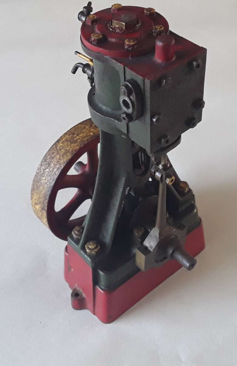
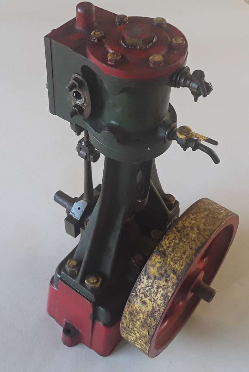
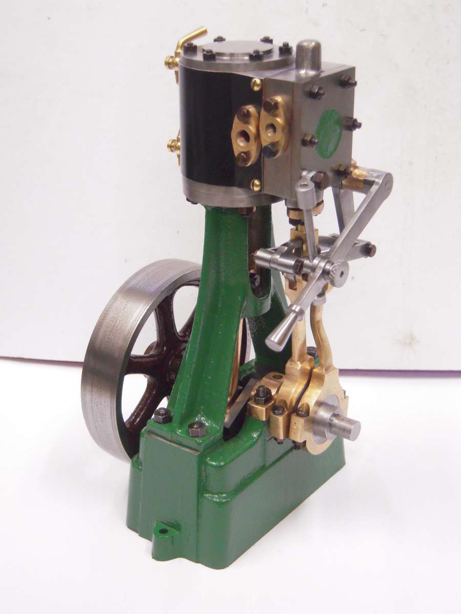
Stuart Turner 7a restoration project
Stuart Turner 7a restoration project
- This topic has 45 replies, 9 voices, and was last updated 13 November 2024 at 14:49 by
 half whit.
- Please log in to reply to this topic. Registering is free and easy using the links on the menu at the top of this page.
Latest Replies
-
- Topic
- Voices
- Last Post
-
-
When is a new 90 degree drill not 90 degrees?
1
2
Started by:
Bill Phinn
in: Workshop Tools and Tooling
- 20
-
10 July 2026 at 13:08
alecs
-
What Did You Do Today 2026
1
2
…
5
6
Started by:
JasonB
in: The Tea Room
- 40
-
10 July 2026 at 11:07
alecs
-
BridgePort Interact 1 Mk2 parameters
Started by:
tomcnc
in: CNC machines, Home builds, Conversions, ELS, automation, software, etc tools
- 1
-
10 July 2026 at 01:31
tomcnc
-
Bridgeport Interact 1 Mark 2 circuit diagrams
Started by:
tomcnc
in: CNC machines, Home builds, Conversions, ELS, automation, software, etc tools
- 1
-
10 July 2026 at 01:16
tomcnc
-
Hole Sizes
Started by:
John Purdy
in: 3D Printers and 3D Printing
- 6
-
9 July 2026 at 21:22
Fulmen
-
A new Milling Machine
Started by:
Martin Johnson 1
in: Workshop Tools and Tooling
- 5
-
9 July 2026 at 20:27
Wade Beatty
-
Tom Senior Vertical Mill Y axis stuck
Started by:
tgglass
in: Beginners questions
- 12
-
9 July 2026 at 19:08
Michael Gilligan
-
Smart & Brown model A spindle lock
Started by:
old mart
in: Workshop Tools and Tooling
- 1
-
9 July 2026 at 18:01
old mart
-
Transformer question
Started by:
Wade Beatty
in: Electronics in the Workshop
- 3
-
9 July 2026 at 17:30
Robert Atkinson 2
-
1930 Austin 12 with 3rd brush dynamo
Started by:
john fletcher 1
in: General Questions
- 14
-
9 July 2026 at 13:21
Russell Eberhardt
-
Impending collapse in NYC
Started by:
Michael Gilligan
in: The Tea Room
- 9
-
9 July 2026 at 12:58
Martin Johnson 1
-
Spindle/bearings fit query for X2 type mill
1
2
3
Started by:
fingerscrossed
in: Manual machine tools
- 14
-
9 July 2026 at 12:47
teamricky
-
24cc DIESEL ENGINE FROM SOLID
1
2
3
Started by:
dean clarke 2
in: I/C Engines
- 13
-
9 July 2026 at 11:47
KEITH BEAUMONT
-
Cotton-covered flex
Started by:
Kiwi Bloke
in: Materials
- 8
-
9 July 2026 at 01:33
Kiwi Bloke
-
Offen imperial bore mic gauge.
Started by:
Graeme Seed
in: Workshop Tools and Tooling
- 6
-
8 July 2026 at 22:27
alecs
-
Lathe coolant applicators
Started by:
lucerne
in: Manual machine tools
- 13
-
8 July 2026 at 10:48
lucerne
-
Flat Surface
1
2
3
4
Started by:
COLIN MARTIN 2
in: Materials
- 36
-
7 July 2026 at 23:34
alecs
-
Hello from new USA member
Started by:
grizmaster
in: Introduce Yourself – New members start here!
- 3
-
7 July 2026 at 22:47
noel shelley
-
Mini-lathe parts source
Started by:
Dunc
in: General Questions
- 2
-
7 July 2026 at 20:37
JasonB
-
McLaren 1,5 inch scale Modl Traction Engine
Started by:
Mike Cooke
in: General Questions
- 1
-
7 July 2026 at 20:08
Mike Cooke
-
Flywheel material
Started by:
Speedy Builder5
in: Materials
- 8
-
7 July 2026 at 19:29
Speedy Builder5
-
Readability / clarity in new combined magazine
1
2
Started by:
Trevor Gale
in: Model Engineer & Workshop
- 19
-
7 July 2026 at 18:24
JasonB
-
Myford Ml7 Technical Drawings
1
2
3
Started by:
Harry Broadbent
in: Model Engineer & Workshop
- 29
-
7 July 2026 at 14:02
Bazyle
-
Identifying the pitch of threading inserts
Started by:
Bill Phinn
in: Workshop Tools and Tooling
- 6
-
6 July 2026 at 20:13
old mart
-
Valuatiion of severql models
Started by:
ron vale 3
in: Stationary engines
- 4
-
6 July 2026 at 19:23
Weary
-
When is a new 90 degree drill not 90 degrees?
1
2
Latest Issue

Newsletter Sign-up
Latest Replies
- When is a new 90 degree drill not 90 degrees?
- What Did You Do Today 2026
- BridgePort Interact 1 Mk2 parameters
- Bridgeport Interact 1 Mark 2 circuit diagrams
- Hole Sizes
- A new Milling Machine
- Tom Senior Vertical Mill Y axis stuck
- Smart & Brown model A spindle lock
- Transformer question
- 1930 Austin 12 with 3rd brush dynamo

