Hi John (And Chris),
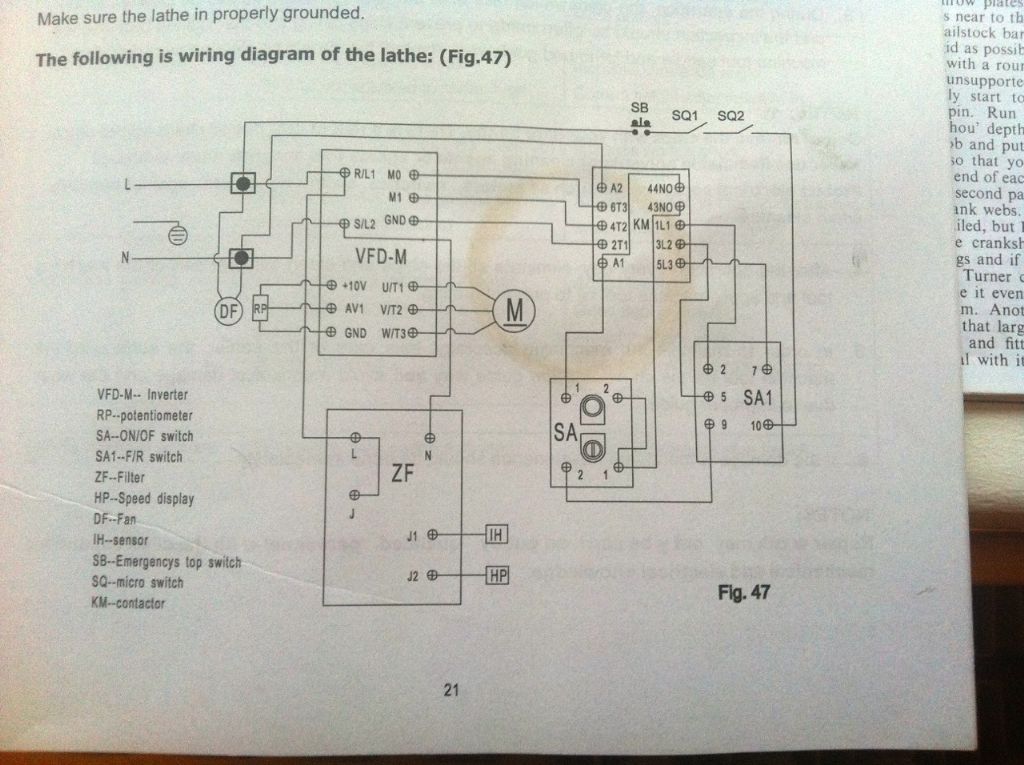
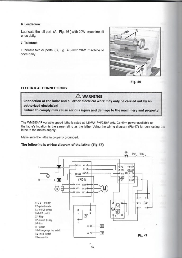
I have found that I have a schematic for the WM250 (VFD version) and I have made some notes in the past.I suspect that the WM280 will be very similar. This is the schematic.

These are the notes I made.
Notes on WM250 schematic
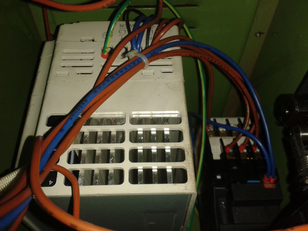
Contactor KM
A1 & A2 are the coil
43 & 44 (NO) are the maintainer contact
Suspect
2T1 & 1L1 Normally open contact
4T2 & 3L2 Normally open contact
6T3 & 5L3 Normally open contact
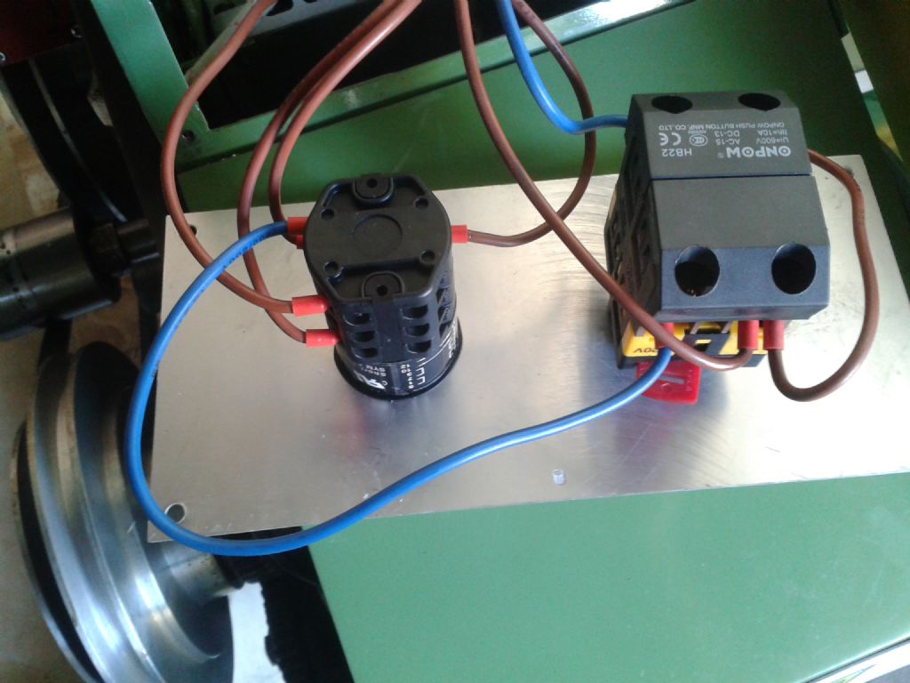
Start/stop switch SA
Start button will be the top two connections (1 & 2) (Normally open contacts)
Stop button will be bottom two connections (1 & 2) (Normally closed contacts)
Suspect that connection 2 is common and 5 and 7 are forward and reverse
Forward/reverse switch SA1
I suspect connections 9 & 10 will be closed in forward and reverse. (And open in the middle position ??)
END OF NOTES.
I think the common, forward and reverse contacts on the switch go to the VFD via three sets of contacts on the contactor.
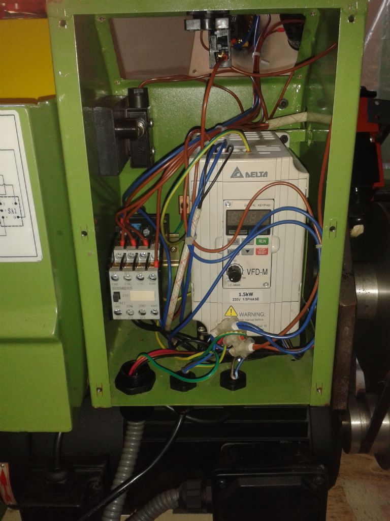
Chris, WITH THE LATHE DISCONNECTED FROM THE POWER can you do the following continuity checks.
Forward/reverse switch Contactor VFD terminals
2 ——————————— 1L1
5 ——————————— 3L2
7 ——————————— 5L3
2T1 ———— GND
4T2 ————- M1
6T3 ————– M2
The if you can manually close the contactor do the following continuity checks while holding the contactor closed.
1L1 to 2T1
3L2 to 4T2
5L3 to 6T3
You should get continuity in all these tests.
Les.
ChrisB.


