Single phase to 3 phase motor conversion.

Advert

Single phase to 3 phase motor conversion.

Home Forums General Questions Single phase to 3 phase motor conversion.

Viewing 25 posts - 1 through 25 (of 31 total)
  • Author
    Posts
  • #333065
    ChrisH
    Participant
      @chrish

      My old Warco 'Economy' mill/drill has a single phase motor. It says it has a 750W motor, but the nameplate is also stamped 6.5 amps and a 90L – 4 frame, both of which suggest to me in my ignorance a 1.5kw motor. However, I don't have the original manual to check what it was sold as but have a Grizzly download manual of the same machine – all versions of the RF 25 I think – and that states a 1 HP motor, which is of course the real money equivalent of 750w. Confusing!

      In the general scheme of things that would be a no worries situation if I didn't want to change things; however, I want to change to a 3 ph motor with a VFD inverter.

      So what do I get? Looking at TEC motors, I could go for a 750w motor, a 1.1kw or a 1.5kw. The 750w is an 80 frame, the 1.1kw could be either a 80 or 90 frame and the 1.5kw is a 90 frame. Plus there is obviously a difference in cost for each power size. I forget what the advantages of a 3ph motor has over a 1ph motor has on power requirement, perhaps that can indicate a direction to go. An 80 frame would obviously have advantages in space requirements as well as cost over a 90, but a bigger power would perhaps have advantages in torque when running at low Hz (low rpm) settings from the VFD.

      What do people think? Those who have done it, why did you go the way you went and did it work out well?

      Chris

      Advert
      #25707
      ChrisH
      Participant
        @chrish
        #333069
        Martin Newbold
        Participant
          @martinnewbold

          Well in my experiance I was told by many people to go for a small motor and small inverter . The motor being of the make you stated in my case was in my opinion faulty and never returned to me. I would not buy another or anything this small in my opinion they are suited for sewing machines. ( I dont want to get into another rant lol did this along time ago and lost money over it) Instead i found a nice 1.5Kw 3PH motor on eBay thats been brilliant.

          Now the odd thing about inverter i have experianced. I decided having not the money to buy a new inverter after it was returned as faulty and delvered back with no faults was to connect it up to this motor. To my suprise this all worked through the gearbox and was not the correct power rating for the motor go figure!. I am not suggesting you do the same as I dont know why this is working as really i should have a 1.5kw inverter. It could be my gearbox is dealing with the torque.

          I guess what i am saying is invest in the best motor and inverter you can afford. its more important really what gearbox you hve it ll connected too.

          Martin

          Martin

          #333106
          Robbo
          Participant
            @robbo

            Doesn't answer your question, but to complicate matters the original Warco leaflet for the Major, Minor, and Economy mills shows the Economy as having a 1/2 HP motor!

            I have a Minor, fitted from the factory with a 1 HP single phase motor. I have in the cupboard a 3-phase 1 HP motor which will replace the single phase 1 HP when I get a round tuit. (I already had the appropriate inverter, which influenced the decision)

            #333109
            Brian Sweeting 2
            Participant
              @briansweeting2

              If it has a 90 frame motor fitted I would replace it with another 90 frame as it would be an exact physical size swap over.

              #333152
              ChrisH
              Participant
                @chrish

                Brian has a point but a smaller physically sized motor does have an advantage for me even though it means a couple of alterations for the foot mounting holes on the motor mounting bracket, as the machine is up against a wall behind it and I have had to relocate the existing motor already to sit to one side of the machine instead of behind as otherwise it wouldn't fit in the space available.

                However, my greater concerns are with the power size, do I stick with 750w (which from Robbo's comment seems to confirm the existing size as stated on the motor) or go to 1.1kw or 1.5kw and the implications of possibly better torque at low revs/hz?

                Chris

                Edited By ChrisH on 21/12/2017 10:31:14

                #333155
                Martin Connelly
                Participant
                  @martinconnelly55370

                  If you are using a VFD and intend to run it below normal speed then you will lose some power. The fix for this is to put in a higher power motor to start with. The extra power will not cause any problems during use. Putting in the lowest power motor you can get away with seems like a case of spend cheap and end up spending twice if you find the low power causes problems.

                  Martin C

                  #333218
                  Simon Williams 3
                  Participant
                    @simonwilliams3

                    I bought one of these machines, albeit with Graham Engineering's "Alpine" badge on it, about 30 years ago. I have recently fitted a three phase 1 kW motor and VSD, and wish I'd conducted the experiment years ago. The machine is much nicer to use, soft start, near instantaneous stop, reversible and only fiddle with changing the belts on the pulleys if you absolutely must. A big improvement all round.

                    There were several learning opportunities along the way. The original single phase motor was 100 frame size, so replacing it with a more powerful motor of a smaller (standard) frame size meant fiddling with the length of the first drive belt. I also found that the shaft size of the original motor was a funny size (22mm I think) whereas the motor I fitted had a 19 mm shaft. So I found myself making a new cone pulley for the motor, which also gave me the chance to gear the drive down a bit so the spindle speeds are not actually like for like with the original selection.

                    However I have achieved what I wanted, which was to be able to drill a (say) 1/2 inch hole in typically two stages without having to swap the drive belts around. The drive belt change for say a 5 mm pilot then a 13 mm drill meant taking both drive belts off; now all I do is leave the drive belt configuration in a lowish speed choice, and twiddle the speed pot from 80 Hz down to 20 Hz or thereabouts.. Sorted.

                    I can still change the drive belts if I want to drill say 20 mm or bigger, but the new 1 Kw motor will even do this at about 20Hz if I'm careful.

                    I'm only using the machine as a drill, usually on mild steel, but fitting a robust VSD to it has made it a much more friendly machine to use and I would recommend it.

                    #333297
                    ChrisH
                    Participant
                      @chrish

                      Simon – your response was just the sort of response I was hoping to get, someone who had been there, done it, and was happy with the result. Sounds like you got an 80 size frame motor of 1kw which is where I was thinking of heading; on reflection I think maybe 1.5 kw would be overkill.

                      Having got a similar set up on my lathe I am both familiar and pleased with the soft start and controllability. I agree with others that a larger motor should/will give better torque at low end speed and hz, which will be good.

                      One query Simon you will be able to answer I hope, is the 3 ph motor a smoother running motor? I am hoping so, the 1 ph motor on the machine now vibrates a fair bit I think, and this seems to transmit via the belts into the whole machine and I don't like that at all.

                      Chris

                      #333401
                      Simon Williams 3
                      Participant
                        @simonwilliams3

                        Good morning Chris, and thank you for those kind words.

                        Firstly I've mislead you slightly, should have checked my facts carefully instead of my memory! The single phase motor I took off was rated at 750 watts, 1420 rpm. The three phase motor I put on is also 750 watts, not I Kw as I stated earlier. The performance of the machine is, however, transformed as I said.

                        As to the matter of vibration, I've seen a lot of stuff to suggest that single phase motors are inherently vibration sources, but I have to say that's not my experience unless there is something actually wrong with the motor. Certainly with this machine the vibration level before I went three phase was not a problem, and fitting a three phase motor hasn't changed that better or worse. But then I only use it for drilling, so I wouldn't notice surface finish problems. Having said that single phase motors don't have a lot going for them, so it may be that the one you've got suffers these problems. If so I'm sure you will see a marked improvement for the upgrade to three phase.

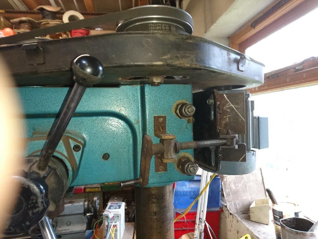
                        My experience is that the drive belts, and maybe the concentricity of the drive pulleys are more of a problem with respect to vibration. The shortcoming of the pulley drive on this machine is that the low speeds use motor drive pulleys far smaller than the realistic minimum size for an A section vee belt, and it's only too easy to let the belt skid on the pulley. This skives a lump out of the side of the vee shape and upsets its smooth running, but it isn't the fault of motor itself. The tensioning arrangement for this machine is pretty crude; it's quite difficult to get enough tension on the belts to transmit the full motor power particularly using the smaller drive pulleys. I made a crude screw tensioner to jack the motor away from the frame of the machine to tackle this problem.

                        dsc_0114-1.jpg

                        As I said, it's a bit crude!

                        Hope this helps, if I can help further do let me know.


                        Best rgds and Happy Christmas to everyone.

                        Simon

                        Edited By Simon Williams 3 on 22/12/2017 12:29:09

                        #333430
                        ChrisH
                        Participant
                          @chrish

                          Simon, I have to agree that belt tightening is not very clever on these machines if yours and mine are anything to go by. The motor belt I can get reasonably tight by pushing hard on the motor whilst doing up the crude adjuster; that was an unexpected bonus of having to resite the motor to the RH side of the mill/drill. The top belts from intermediate pulleys to spindle pulleys are a pain – having to stand on a stepladder and slacken two socket head bolts, try and hold the intermediate pulleys with sufficient tension whilst tightening one of the socket head bolts is awkward to say the least. Your excellent belt tightener idea would be very useful on this section of belt drive Simon. I get a bit of vibration from the belts but very rarely belt slip, and I can see the motor is vibrating a little too. I am sure a 3 ph motor will not vibrate nearly so much and will run a lot smoother. A 3ph motor with a VFD will make changing that belt and re-tensioning a greatly reduced occurrence, as you have pointed out.

                          Do you find that the 0.75kw motor on low Hz, say between 10 and 25 Hz, lacks torque when doing meaty cuts Simon? Because with respect to motor size, my thoughts of yesterday are now back in for re-negotiation, and part of my worry is low Hz torque with the 0.75kw motor.

                          The motor that would fit without any alterations would be the 1.5kw motor (I'm looking at TEC motors). But that is double the original 1ph motor and maybe a bit of an overkill. The 0.75kw motor would match the power size of the original and would be way smaller physically, which would be nice, but would it have the torque at low Hz running speeds? The 1.1kw motor is more similar sized physically to the 1.5kw motor, would presumable give more low down Hz torque, but would need the mounting feet holes in the brackets altering, which would not be a problem if one had another drilling machine or has faith in the ability to drill 12mm holes accurately with a 3/8" electric drill and a 1/2" battery drill which is all I have available in the absence of the mill/drill; not insurmountable, just blooming awkward. Plus, there is a cost element to factor in, like the 1.5 motor is £37 more than the 0.75kw motor, a not insignificant sum.

                          So, I'm back to, do I go with 0.75kw and risk insufficient low Hz torque, 1.1kw and buggar about with drilling holes or 1.5 kw, overkill and £37 poorer? If money was no object it might be an easy choice in one way, but would it be the right one? Perhaps I need to speak to TEC after Christmas and see what their views are on running their motors on VFD's at low Hz are re torque. One thing I do like about TEC motors, amongst others, is that the feet can be relocated 180 degrees around the motor body to move the connection box to the best, or least awkward, place, which will help me and is not available on the 1ph motor fitted.

                          Chris

                          Edited By ChrisH on 22/12/2017 15:58:13

                          #333432
                          John Haine
                          Participant
                            @johnhaine32865

                            When I converted my Myford VMB, it had one of these intermediate pulley malarkeys which was a pain to adjust. It also had a rather small step pulley on the motor, which wouldn't be suitable for the new 3 phase drive. So I ditched the intermediate pulley and used it on the new motor as it was 4-step and the same size as the spindle pulley. I also made my life simpler by fitting a link belt. Result, easy belt changing (when it's needed which is seldom), and a smooth and quieter mill.

                            #333454
                            Simon Williams 3
                            Participant
                              @simonwilliams3

                              Well, my take on this is that throwing away the low gearing means forfeiting the torque reserve of the original machine. If I'm fitting a VSD I would prefer to gear the machine LOWER than the original, and use the variable speed facility to increase the speed back to where we started. That way the torque fade off as you reduce the motor drive speed is pushed out of the way to some extent. It's all a bit subjective – you soon learn what the machine will let you do and treat it accordingly.

                              But it does depend on what you want to do with the machine. When I first bought mine one of the jobs I did with it was to carve two four inch diameter holes through a one inch thick mild steel disc, part of a home made wood chipper. The torque requirement to ensure that the fly-cutter didn't stall part way through meant it needed the low gearing of the intermediate pulley system. These days I'd do that job a different way, but stick an inch and a quarter drill in the spindle and go chewing, you still need a fair bit of torque to make sure the tool doesn't stall out. If it stalls of course you usually chip the edge, so that slows things down somewhat. High speed tools like being run slowly at moderately high feed rates, you can't achieve that without the torque reserve of low gearing.

                              So the point of my reply earlier was to assure you that my experience with a 750 W motor was all good, and I wouldn't bother with going to 1500 watts myself, particularly if I was buying the motor specially. If I had one under the bench looking for a good home, now that's a different matter. I haven't found myself in the "insufficient low speed torque" syndrome, I expect I could find it if I went looking but one needs to be realistic about how stiff that round column is and how much the machine will stand. Grinding the tool so it cuts freely without being too greedy helps.

                              If you ever leave the upper belt guard off don't fit a link belt, your hair line is too close to the action. Not sure I see the attraction of a link belt in this application, an endless belt just slips over the driver and driven sheaves.

                              If you want to change the bolt hole centres for mounting the new motor on the existing plate, can you pre-make a sub plate using the drill as is, then simply do a dismantle/reassemble job? I found more difficulty and fiddling about in the motor shaft sizes being different, which lead me to make a new cone pulley.

                              To solve that problem I bought a taper lock bush and pulley corresponding to the biggest diameter of the motor cone pulley, then turned up the other three sheaves as a lump and bolted them axially on top of the taper lock. I used a radial key let into the face of the taper lock to ensure a positive drive. The minor diameter of the smallest sheave of the motor pulley was smaller than the motor shaft diameter, so the two smallest sheaves overhang the end of the motor shaft.

                              Hope this helps

                              Rgds Simon

                              #333457
                              John Haine
                              Participant
                                @johnhaine32865

                                Link belt – adjustable, smooth running. Agree I wouldn't run the machine without a guard on it!

                                #333493
                                ChrisH
                                Participant
                                  @chrish

                                  I have calculated the likely speed ranges, using a set ratio on the intermediate to spindle pulleys and just using the top, third and fourth down pulley sheaves on the motor spindle with a 3ph motor and VFD. This calculation showed that 100rpm spindle (quill) speed could be achieved by 20Hz on a 4 pole motor; in other words, plenty of torque for the vast majority of time, so a 0.75kw motor would be OK I think. On the odd occasion I would need more torque I will just have to take lighter cuts, which is my natural fallback anyway, so no problem there! Re the hole drilling, yes, further thought has suggested that if planned properly with some forethought then the work sequence is eminently doable with the kit I have, so another plus for the 0.75kw motor instead of a bigger one.

                                  The regime I am looking at would see the belt on the intermediate to spindle being set for the vast majority or work and only the motor belt being changed, utilising the top, third and fourth pulley sheaves which are relatively easy and quick to change using two belts, one for the top and another for the bottom two sheaves, and therefore no worries there to do. Only very really do I envisage a situation where the intermediate to spindle belt would need to be changed. I have thought in the past of using a link belt to reduce vibration, but have not bought one yet to try; if I did I take note of the warnings to use the belt guard!

                                  It maybe that I need to make another motor pulley sheave set and would tackle that when the need arose, but forewarned is forearmed and I will look at that possibility ahead of time I think. I do thank you, all who replied but Simon in particular, for the help and advice you all have provided.

                                  Chris

                                  #333508
                                  Ray Lyons
                                  Participant
                                    @raylyons29267

                                    I bought a Sealey Mill/Drill fitted with a 1HP motor about 20 years ago and carried out several modifications to achieve a reasonable finish when milling. About 10 years ago, one of my friends was throwing out a 1 1/2 HP 3 ph motor so I took it off his hands and overhauled it stripping down and turning the shaft to fit the motor pulley.

                                    Buying a second hand controller on EBay, the whole thing cost me less than £50. With the extra power and the speed control, I rarely change the belt position which is in the middle range. Now I would not be without it but then I went for the very cheap option. Even if you do decide to buy everything new, I feel sure you will not regret it as the conversion enables speeds to be adjusted for the size of cutter with plenty of power to cope.

                                    #476013
                                    Rodney Markham
                                    Participant
                                      @rodneymarkham24353

                                      I am trying to fix a converter for a young friend, it seems a very simple design, just a transformer and 4 capacitors. The front panel has a 3-position level switch and a boost button.

                                      Can you identify this devise?

                                      Is it possible to convert single phase to 3 with above components?

                                      What is the boost button for?

                                      #476049
                                      SillyOldDuffer
                                      Moderator
                                        @sillyoldduffer
                                        Posted by Rodney Markham on 30/05/2020 09:29:01:

                                        I am trying to fix a converter for a young friend, it seems a very simple design, just a transformer and 4 capacitors. The front panel has a 3-position level switch and a boost button.

                                        Can you identify this devise?

                                        Is it possible to convert single phase to 3 with above components?

                                        What is the boost button for?

                                        It sounds like a phase convertor similar to this Clarke model sold by MachineMart. Their Manual includes a circuit diagram and operating advice. This sort of convertor produces imperfect 3-phase with an auto-transformer and capacitors. Two good phases and the third is 'sort of'. How well it works depends on the 3-phase load – they aren't suitable for everything. The level switch is adjusted for best results, which will probably match the HP of the motor.

                                        The capacitors have a very hard life and are likely to fail; some users report a working life of about 3 years. Replacements are widely available.

                                        Not sure about Boost. I think it's pressed to help a reluctant motor to start. Massive current is drawn briefly as the motor fires up, so the convertor has the wherewithal to deal with a temporary start condition.

                                        As a new set of capacitors may cost about £100, may be worth considering a VFD instead.

                                        Dave

                                        #476098
                                        Rodney Markham
                                        Participant
                                          @rodneymarkham24353

                                          Thanks Dave,

                                          This one only has a transformer and capacitors, certainly no bridge rectifier. I'll draw the circuit diagram later, not sure how to load it up to this chat but I'll have a go.

                                          #476107
                                          SillyOldDuffer
                                          Moderator
                                            @sillyoldduffer

                                            Posting photos, only jpegs are allowed, described here.

                                            The bridge rectifier in the Clarke circuit isn't part of the phase converter as such. It operates a relay that cuts the power when a problem is detected. Another make of Phase Convertor is likely to be different, maybe not having any cut-out circuitry at all. But the auto-transformer, switch, and capacitor circuitry should be similar in all of them.

                                            I think I'm right in saying these units need a load to work; if bench testing, attach a motor, or maybe three lamps. With luck an expert will be along to help soon!

                                            Dave

                                            #476117
                                            old mart
                                            Participant
                                              @oldmart

                                              Make a note of the spindle diameters of your motor and see if it is the same as the candidate motor. Are you in a position to do any modifications? The projection of the spindle should also be checked. As these drill mill motors are usually in an accessible position at the back of the machine, changing it should be fairly straightforward.

                                              I would opt for a 0.75 Kw motor. I chose a 0.75Kw for the Tom Senior R8 conversion and find the power is just right, it is easy to back off a tiny bit if anything starts to sound strained.

                                              That 6.5A may be the starting current for your motor.

                                              The motor I chose is a six pole TEC which runs at 935rpm @50Hz. I run it between 25 and 75 Hz (467 to 1402rpm). The motor will run slower, but looses a lot of torque, and cooling is compromised. The pictures of this particular motor show the end mount which I required, but it came with detachable feet. The original belt speed change is still used in addition to the VFD. Check out the VFD range from the same supplier, I bought a Schnieder Altivar 0.75 Kw from them and their "quick start guide" made wiring and programming so easy.


                                              **LINK**

                                              Edited By old mart on 30/05/2020 14:44:07

                                              #476152
                                              Rodney Markham
                                              Participant
                                                @rodneymarkham24353

                                                Thanks Dave,

                                                I'll dig out some lamps and connect in star (I presume)

                                                #477260
                                                Rodney Markham
                                                Participant
                                                  @rodneymarkham24353

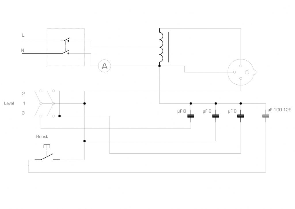
                                                  circuit diagram.jpg

                                                  #477263
                                                  Rodney Markham
                                                  Participant
                                                    @rodneymarkham24353

                                                    Above is the circuit diagram, very basic bit of kit.

                                                    The Clarke converter pointed out by Dave, looks to like the converter starts up with one set of capacitors and then switches over to more or whatever.

                                                    I have connected 3no. 60Wh filament bulbs, 1 gets over 300v the other about 85v (according to my multi meter)

                                                    The 100 -124 Mf capacitor is a motor start, my multi meter on capacitance range only gives me a nF reading, the 8Mf read about 7 and a bit.

                                                    I haven't put my meter across all the other capacitors, has anybody got any better suggestions?

                                                    #477267
                                                    Robert Atkinson 2
                                                    Participant
                                                      @robertatkinson2

                                                      Well that circuit applies 180 degrees to two phases (should be 120) and about 90 to the other. not an ideal situation.
                                                      The capacitor that reads in nF range is faulty. The 8uF are about right, tolerace is tpically +- 10% and normally under. Note that it's not just capacitance and basic voltage rating that matter when replacing. It must be rated for motor starting applications.

                                                      Robert G8RPI.

                                                    Viewing 25 posts - 1 through 25 (of 31 total)
                                                    • Please log in to reply to this topic. Registering is free and easy using the links on the menu at the top of this page.

                                                    Advert

                                                    Latest Replies

                                                    Home Forums General Questions Topics

                                                    Viewing 25 topics - 1 through 25 (of 25 total)
                                                    Viewing 25 topics - 1 through 25 (of 25 total)

                                                    View full reply list.

                                                    Advert

                                                    Newsletter Sign-up