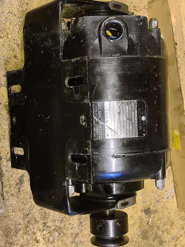
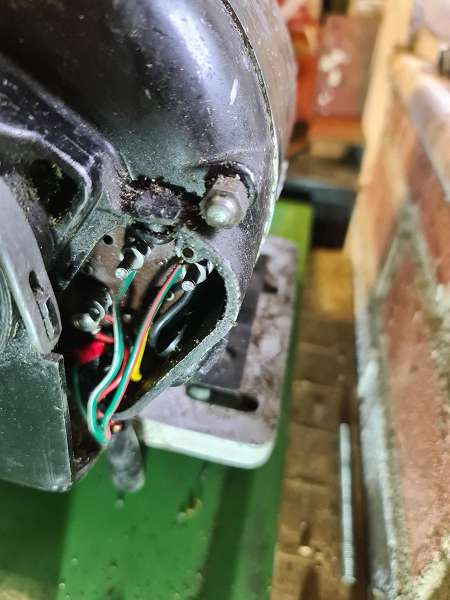
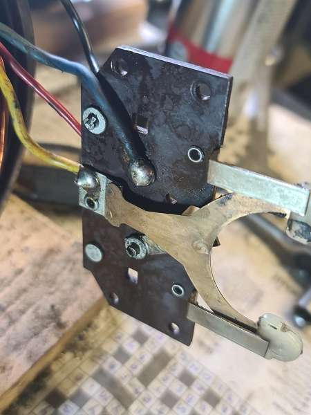
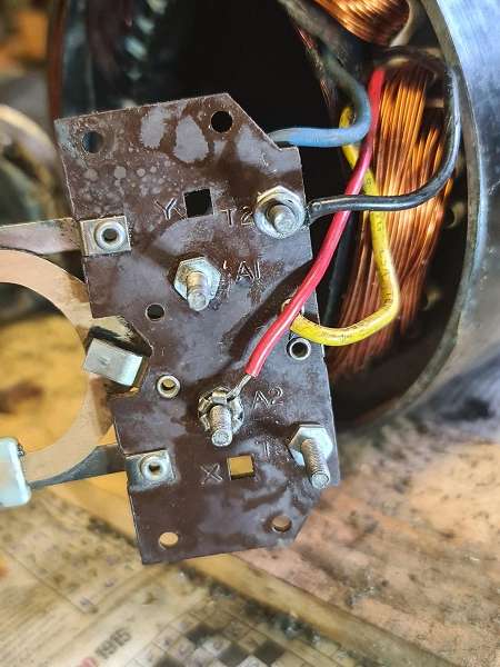
motor and switch wiring Myford ML7
motor and switch wiring Myford ML7
- This topic has 13 replies, 7 voices, and was last updated 27 July 2025 at 13:56 by
 1957jmh.

- Please log in to reply to this topic. Registering is free and easy using the links on the menu at the top of this page.
Latest Replies
-
- Topic
- Voices
- Last Post
-
-
End Mill Sharpening Jig
Started by:
Vic
in: Workshop Tools and Tooling
- 6
-
19 August 2025 at 23:02
Nigel Graham 2
-
Use of Hydrostatic lubrication in steam locomotives
Started by:
Greensands
in: Locomotives
- 5
-
19 August 2025 at 22:38
Richard Simpson
-
Horwich Crab
Started by:
Michael Foster
in: Locomotives
- 2
-
19 August 2025 at 22:17
Dave Wootton
-
The stand alone weight for tower clock
Started by:
dk0
in: Clocks and Scientific Instruments
- 6
-
19 August 2025 at 22:12
dk0
-
Solar panel
Started by:
duncan webster 1
in: Electronics in the Workshop
- 4
-
19 August 2025 at 20:37
martin haysom
-
Kuroda Boring & Facing head
Started by:
Oily Rag
in: Workshop Tools and Tooling
- 7
-
19 August 2025 at 20:18
ryan.carter848
-
Cheap DRO
Started by:
Steve355
in: General Questions
- 11
-
19 August 2025 at 19:42
SillyOldDuffer
-
Opposed Piston Engines
1
2
Started by:
Richard Simpson
in: The Tea Room
- 13
-
19 August 2025 at 19:31
Andy Stopford
-
Any suggestions
Started by:
Vic
in: The Tea Room
- 6
-
19 August 2025 at 17:53
DMB
-
Greatest Model Engineer
Started by:
Juddy
in: The Tea Room
- 14
-
19 August 2025 at 17:40
Pete
-
New Compressor
Started by:
Andy Brocklehurst
in: General Questions
- 16
-
19 August 2025 at 17:13
not done it yet
-
St Albans Big Show 27 & 28 Sept 25
Started by:
Bazyle
in: Exhibitions, Shows and Club Events
- 2
-
19 August 2025 at 14:20
Bo’sun
-
Making Unimat DB/SL Steadies
1
2
Started by:
Andy Carlson
in: Workshop Techniques
- 12
-
19 August 2025 at 13:44
duncan webster 1
-
Backplate
Started by:
Steve355
in: General Questions
- 10
-
19 August 2025 at 13:12
JasonB
-
Steam driven air pump for brakes
Started by:
Werner Schleidt
in: Locomotives
- 10
-
19 August 2025 at 13:07
Martin Johnson 1
-
Harold Hall – 1933 -2024
Started by:
Neil Wyatt
in: Website Announcements
- 13
-
18 August 2025 at 18:24
Vic
-
My week this week! My workshop videos
1
2
…
11
12
Started by:
Phil Whitley
in: The Tea Room
- 16
-
18 August 2025 at 17:20
vic newey
-
Who’s to be trusted ?
1
2
Started by:
Michael Gilligan
in: Electronics in the Workshop
- 18
-
18 August 2025 at 16:01
HOWARDT
-
NU tool milling machine
Started by:
joseph tatler
in: Manual machine tools
- 7
-
18 August 2025 at 11:11
Martin Connelly
-
Model Engineer Magazine Collection
Started by:
mfengine1
in: Books
- 10
-
18 August 2025 at 09:33
bcaddle62
-
Building Bernard Tekippe’s Precision Regulator
1
2
…
5
6
Started by:
Chris Raynerd 2
in: Clocks and Scientific Instruments
- 14
-
18 August 2025 at 03:37
Michael Gilligan
-
Herbert B Drill Pulley and Lubrication
Started by:
Steve Hunt
in: Help and Assistance! (Offered or Wanted)
- 3
-
18 August 2025 at 00:24
Steve Hunt
-
3 phase supply (again)
1
2
3
Started by:
colin hamilton
in: General Questions
- 21
-
17 August 2025 at 19:33
mark costello 1
-
Vickers Inverted Engine
1
2
3
Started by:
JasonB
in: Stationary engines
- 11
-
17 August 2025 at 19:29
JasonB
-
Henry Buckeldee
Started by:
Michael Gilligan
in: The Tea Room
- 1
-
17 August 2025 at 16:03
Michael Gilligan
-
End Mill Sharpening Jig


