how to machine an internal curve

Advert

how to machine an internal curve

Home Forums Workshop Techniques how to machine an internal curve

Viewing 15 posts - 26 through 40 (of 40 total)
  • Author
    Posts
  • #370700
    Sam Longley 1
    Participant
      @samlongley1
      Posted by John Haine on 06/09/2018 14:40:36:

      As you asked how we would do it, my answer is I'd simply use a Mach3 wizard to generate code to drive my CNC lathe.

      id_curve.jpg

      The picture is a screen grab of the relevant wizard. I've used this to make similar internal circular fillets on a part made from SS.

      And how would you calculate sufficient clearance on the underside & side of the cutter to allow for the internal radius of the cut . or is that not a problem – presumably you still have to make an allowance of some sort as you would with any boring bar. Bearing in mind that the internal hole is 12mm.


      Edited By Sam Longley 1 on 06/09/2018 18:37:54

      Advert
      #370704
      JasonB
      Moderator
        @jasonb

        You would just pick a boring bar that will fit down a 12mm hole.

        #370711
        Neil Wyatt
        Moderator
          @neilwyatt

          I'd:

          Machine inside radius with form tool, part off, reverse and machine other side of inside.

          Fit to a suitable mandrel, then machine outside with a pair of form tools.

          Assumes small enough for form tools to be a practical proposition.

          Neil

          #370712
          JasonB
          Moderator
            @jasonb

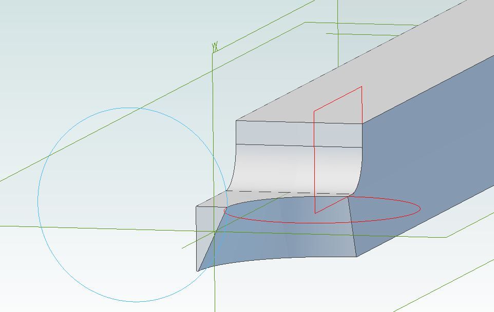
            Sam, you asked about grinding a tool earlier. This is the sort of thing you would need, I went for 8mm square so it's fairly rigid then ground the end down to 4mm thick. The red circle represents your desired 6mm corner radius and the blue circle is your 12mm central hole. You will need to grind about 25degrees clearance on the curved cutting edge so that the bottom corner of the tool will not foul the 12mm hole.

            roundover.jpg

            #370714
            Anonymous

              I wouldn't grind a relief angle, I'd make the relief curved and of slightly smaller radius that the hole. That way the cutting edge is stronger. thumbs up

              Andrew

              #370715
              JasonB
              Moderator
                @jasonb

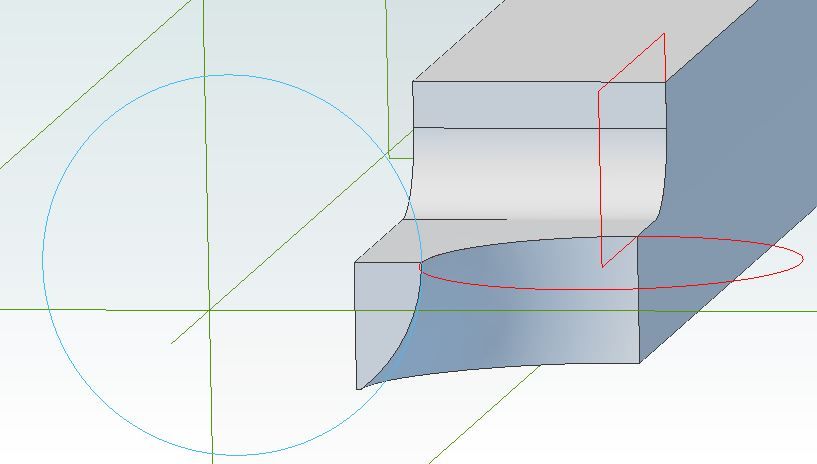
                I did try that but was rotating th ectr of the profile and got a weak pointed end but should have revolved the edge of the profile which gives this

                roundover2.jpg

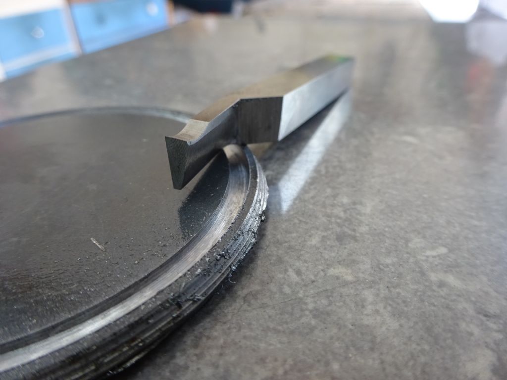
                Much like the clearance on a trepanning tool but for a tighter radius

                dsc02964.jpg

                #370717
                David George 1
                Participant
                  @davidgeorge1

                  Why do you want to make them from stainless as the originals were made from alloy much easier to manufacture and just hard anodise to prevent wear.

                  David

                  #370733
                  Bill Pudney
                  Participant
                    @billpudney37759

                    Does anyone actually do hard anodising in the home workshop?? As far as I remember it's a far more difficult process than cosmetic or normal anodising.

                    cheers

                    Bill

                    #370839
                    Sam Longley 1
                    Participant
                      @samlongley1
                      Posted by JasonB on 06/09/2018 20:10:35:

                      I did try that but was rotating th ectr of the profile and got a weak pointed end but should have revolved the edge of the profile which gives this

                      roundover2.jpg

                      Much like the clearance on a trepanning tool but for a tighter radius

                      dsc02964.jpg

                      Thanks

                      that is what I needed I can visualise that much better now. Never thought of drawing it out like that. Obvious when one thinks about it logically. I note that the top is flat on the drawing- is that correct?The bevel on the example below would not be correct – or would it?

                      Sam L

                      Edited By Sam Longley 1 on 07/09/2018 19:13:59

                      #370845
                      Sam Longley 1
                      Participant
                        @samlongley1
                        Posted by David George 1 on 06/09/2018 20:37:40:

                        Why do you want to make them from stainless as the originals were made from alloy much easier to manufacture and just hard anodise to prevent wear.

                        David

                        I suspect that it is something more than just a piece of aluminium. Bearing in mind that these can be turned out in their 1000s on CNC equipment they should be cheap to produce. However, in spite of quite a few manufacturers making them they still retail (this size) in the £ 12-00 each range. Larger ones quickly reach £ 20-00 plus. They take a lot of load & the ropes make a lot of friction & heat.

                        That suggests to me that there must be something in the construction that is inflating the cost & preventing competition reducing the price. The material & its treatment perhaps!!!!

                        I am proposing to use SS as I have this available & it will be strong enough.I really only want to make a dozen so I can say "Because I can" which is probably why a lot of forumites make stuff.

                        Sam L

                        #370851
                        JasonB
                        Moderator
                          @jasonb

                          You would probably want a bit of top rake although I did not draw it on the sketch.

                          The photo of the tool would not work on such a small hole as yours, that groove in the disc was cut with it and is about 70mm dia

                          #370853
                          John Haine
                          Participant
                            @johnhaine32865

                            I think everyone has focused on how to turn the internal curve on the first face. The external curve is quite interesting. How one does the other "end" after parting off is more challenging – how grip the part for the second operation?

                            #370856
                            JasonB
                            Moderator
                              @jasonb
                              Posted by John Haine on 07/09/2018 19:57:54:

                              I think everyone has focused on how to turn the internal curve on the first face. The external curve is quite interesting. How one does the other "end" after parting off is more challenging – how grip the part for the second operation?

                              I'd do one internal edge, part off and then do the other internal edge which will be easy to hold by the OD.

                              Then a simple arbor with 12mm spigot, nut and washer will allow access to the OD.

                              #370857
                              Neil Wyatt
                              Moderator
                                @neilwyatt

                                They surface treat the anodising with teflon to reduce friction.

                                > how grip the part for the second operation?

                                As I suggested earlier, a mandrel through the middle, perhaps a taper and an opposing one on the nut.

                                Neil

                                #370863
                                Sam Longley 1
                                Participant
                                  @samlongley1

                                  So far it seems I have to follow the procedure— bore the hole, cut the inner curve on one side, part off. Turn round & grip in chuck nice & square to the axis, machine other half of round. Undertake any smoothing out where the 2 curves meet to avoid any edges. Suppose some form of "lapping" but not sure quite how yet.

                                  Mount onto a tapered male mandrel & drive up with a special nut that has a female part & square shoulder to make sure it stays square to the axis. Turn the outer groove, using a parting tool & Jason's step method, then need to either grind a piece of tool steel or purchase a circular tipped cutter smaller than the finished size to polish up. Finish off with a round file if there are any chatter marks.

                                  Take it down the yacht club & say " look what i made- only cost me 30 bob in material"     (yes I tell lies as well!!)

                                  Insert somewhere above as appropriate —"Curse, throw it in the bin, have a cup of coffee & start again"frown

                                  Edited By Sam Longley 1 on 07/09/2018 20:43:40

                                Viewing 15 posts - 26 through 40 (of 40 total)
                                • Please log in to reply to this topic. Registering is free and easy using the links on the menu at the top of this page.

                                Advert

                                Latest Replies

                                Home Forums Workshop Techniques Topics

                                Viewing 25 topics - 1 through 25 (of 25 total)
                                Viewing 25 topics - 1 through 25 (of 25 total)

                                View full reply list.

                                Advert

                                Newsletter Sign-up