Lathe steady position

Lathe steady position

Home Forums Beginners questions Lathe steady position

Viewing 20 posts - 1 through 20 (of 20 total)
  • Author
    Posts
  • #426549
    Keith Matheson
    Participant
      @keithmatheson47708

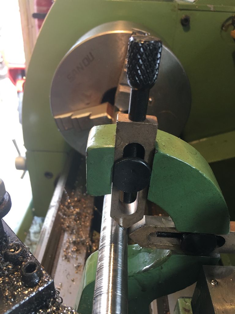
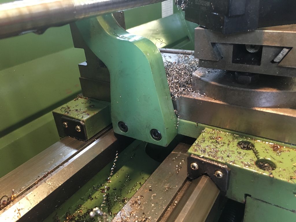
      c7cad021-063e-4043-9fa6-f4a02850ee2f.jpegHi, after a couple years of use of use (I know , I know) I have finally got around to trying out the lathe steady on my toolco 1130. After fixing it to the saddle it appears not to line up with the part being turned. Is this normal? ( hopefully photo attached) if the holes in the saddle are in the incorrect place I assume the easiest way to fix this would be to put slots in the stead6 and move it along to the corrc5 positioning?754ddf52-c70c-4ed7-b1af-2486f3adb3c2.jpeg

      #9835
      Keith Matheson
      Participant
        @keithmatheson47708
        #426551
        Emgee
        Participant
          @emgee

          Hi Keith, looks to me the fixing holes are in the wrong place on the steady.

          If you remove the fixing screw closest to the operator and swivel the steady until the top finger is vertical to the lathe bed it may then also be on the centre line, also the back finger needs to be on work centre.

          If that is the case you could redrill the steady for the fixing screw removed, you may have to plug the original hole for security of the steady.

          Emgee

          #426558
          Andrew Moyes 1
          Participant
            @andrewmoyes1

            It certainly looks like an error in manufacture. That will be tricky to sort by redrilling. Perhaps an easier solution would be to make new fingers with offset ends. Or modify the existing ones by soldering flat pads onto the ends, marking where they touch the workpiece and angling the ends to suit.

            #426560
            PekkaNF
            Participant
              @pekkanf

              Would It be possible to fit approximately 10 mm sandwich plate and not to use the original erroneous screw locations but make new ones furher away (and possibly Low Hex Head Screws or countersunk head screws)?

              Maybe you need to make back fixing point trough the steady and sandwich plate, maybe there is enough space outside of the fixed steady?

              This would allow to fix this steady to to sandwich plate first and then make fresh start for new fixing screws. Allows using the new (better and more locating postitions) for mounting and removing the fixed steady and allows better location fixing for news holes. I would put good size arbour between chuck and tail stock, locate steady fingers to near ideal places, CA glue the steady onto cross slide and then mark location for fresh screws.

              Downside is that a sandwich plate moves the fingers away from the cutting tool, sometimes it is problem, sometimes not really that much.

              #426573
              JasonB
              Moderator
                @jasonb

                I think I would just mill the holes into slots to slide it forwards the 4-5mm needed.

                Make sure the holes in the steady don't have excess filler or paint in them which may be throwing things out a bit.

                #426580
                Pete Rimmer
                Participant
                  @peterimmer30576

                  Looks like the wrong steady or a badly drilled apron.

                  I would mill an inch wide flat across the holes to the depth of the counter-bore. Slot the holes to let the steady slide forwards into alignment and make a clamp plate to span the slots.

                  Before doing that, or lacking milling facilities, I would clamp it up with the front bolt only and see if it will rotate into a suitable position. If it does, re-drill the back hole further inboard.

                  #426599
                  Neil Wyatt
                  Moderator
                    @neilwyatt

                    To me the front fixing hole in the steady looks 1-2mm higher than the back one. This would lean the steady back and displace the finger 3-6mm from the right position.

                    Neil

                    #426600
                    Nick Clarke 3
                    Participant
                      @nickclarke3

                      Neil – wouldn’t a hole higher up the steady move it towards the lead screw not away??

                      #426610
                      thaiguzzi
                      Participant
                        @thaiguzzi

                        Not wanting to sound thick, but what if the fingers were repositioned in the photo so that horizontal was at 3 o clock ( but pulled backwards) enabling vertical to be 12 o clock rather than 1 o clock. Looks to me if horizontal finger adjustment is "reduced", everything should line up.

                        Or have i missed something?

                        #426616
                        Jeff Dayman
                        Participant
                          @jeffdayman43397

                          For a simpler repair approach the top finger could be removed, built up on the front side with weld, then ground to an appropriate shape with the tip on vertical centre.

                          Or you could make a set of fingers with ball bearings instead of direct contact fingers – and place the pivot holes for the bearings at correct positions.

                          Just food for thought.

                          #426622
                          old mart
                          Participant
                            @oldmart

                            I would try testing what would happen if the front hole in the steady was repositioned. Looking from the chuck side, the steady minus the front screw could be pivoted until the vertical finger is directly above the spindle axis. At this point, the horizontal finger should be checked to see if it is in line with the spindle in the horizontal axis. If those two positions can be achieved, then the front screw position in the steady can be remachined. The new hole at the front of the steady will be further from the edge where there is plenty of meat.

                            #426676
                            Keith Matheson
                            Participant
                              @keithmatheson47708

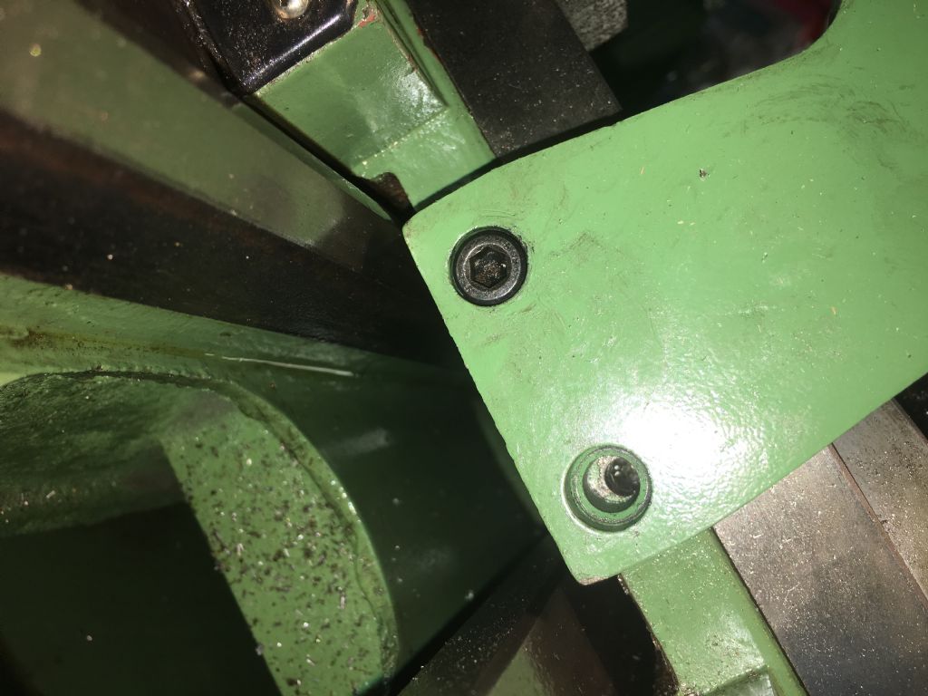
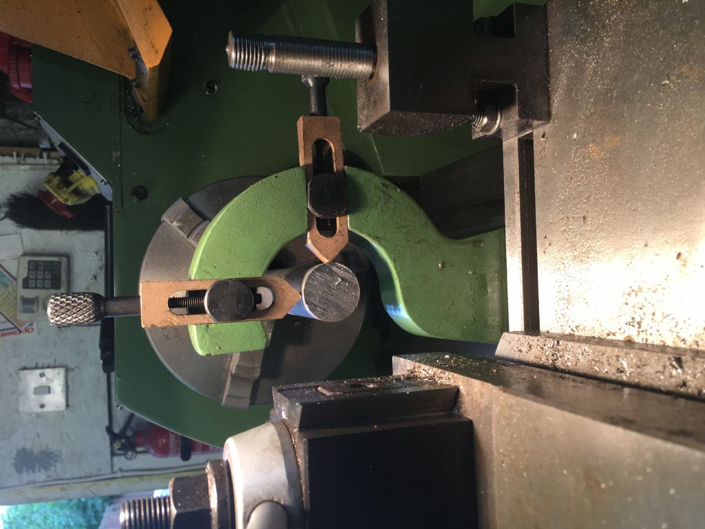
                              Thank you all for taking the time to read my post and to offer great guidance ( as usual ) Due to this I can take look tomorrow and see if the two fixing screws are horizontal and establish where the ‘ three o'clock ‘ finger is actually pushing on the part. I will report back tomorrow and hopefully discuss a simple fix. Thanks again. Keith mm
                              #426725
                              Pete Rimmer
                              Participant
                                @peterimmer30576

                                When you're lining it up use a smallish piece of stock in the chuck to do it. Alignment is more critical as the diameter of the part decreases.

                                #426731
                                Neil Wyatt
                                Moderator
                                  @neilwyatt
                                  Posted by Nick Clarke 3 on 30/08/2019 13:25:38:

                                  Neil – wouldn’t a hole higher up the steady move it towards the lead screw not away??

                                  Good point. It's clearly fubared….

                                  Neil

                                  #426732
                                  Neil Wyatt
                                  Moderator
                                    @neilwyatt
                                    Posted by thaiguzzi on 30/08/2019 14:38:13:

                                    Not wanting to sound thick, but what if the fingers were repositioned in the photo so that horizontal was at 3 o clock ( but pulled backwards) enabling vertical to be 12 o clock rather than 1 o clock. Looks to me if horizontal finger adjustment is "reduced", everything should line up.

                                    Or have i missed something?

                                    Yes – it's fixed to the saddle not the carriage so you can't move the body of the steady back and forth.

                                    #427140
                                    Keith Matheson
                                    Participant
                                      @keithmatheson47708

                                      2ec6245d-485c-459e-bdff-b0eea9fc4ae2.jpegI have bolted the steady with the one rear bolt and then twisted the steady until the fingers were at 12 o’clock and three ( by eye). As you can see from the photos the unbolted front hole does not line up with the tapped hole on the saddle. Well spotted that man! How accurate does my fixing of the hole need to be? I have a mill so tempted to make the front hole in the steady a slot and then move steady to position by eye (ie adjust to ge 12 and 3 o’clock for the fingers). Solutions gratefully received. Keith mm dcdfa42b-6145-4175-8b46-9d14e32af83c.jpeg

                                      #427154
                                      Emgee
                                      Participant
                                        @emgee

                                        Keith

                                        If you clean off the cross slide and lay a steel rule on the top of the cross slide and touching the steady you can scribe a fine line from front to back on the steady.
                                        Remove the steady and measure to the centre of the hole from the top face of the cross slide, add the thickness of the rule used to scribe the line, this will give you the distance from the scribed line on the steady to the centre of the new hole neede to fix the steady in the new position.
                                        Measure the centre distance of the fixing holes and transfer the dimension to the steady so you get the new hole in the desired place.

                                        As I said earlier you may have to plug the existing hole before drilling the new one to ensure the hole stays on the marked centre.
                                        Counterbore for the setscrew head while set up for the fixing hole.

                                        Emgee

                                        Edited By Emgee on 02/09/2019 21:11:53

                                        #427264
                                        old mart
                                        Participant
                                          @oldmart

                                          If you reposition the front hole using your mill, it would be better if it and the counterbore were bigger and a custom screw were made. Or a stepped bush, perhaps. As already mentioned, use a small diameter test bar in the chuck or tailstock to get a more accurate visual idea of when both fingers are aligned. If the centre lines can be got within 1mm, you should be good to go.

                                          #427337
                                          Keith Matheson
                                          Participant
                                            @keithmatheson47708

                                            Many thanks Emgee and ‘old mart’. Your guidance is duly noted and I will embark on the modifications safe in the knowledge I have been wisely guided. Keith mm

                                          Viewing 20 posts - 1 through 20 (of 20 total)
                                          • Please log in to reply to this topic. Registering is free and easy using the links on the menu at the top of this page.

                                          Latest Replies

                                          Home Forums Beginners questions Topics

                                          Viewing 25 topics - 1 through 25 (of 25 total)
                                          Viewing 25 topics - 1 through 25 (of 25 total)

                                          View full reply list.