Warco WM180 4 way tool post

Warco WM180 4 way tool post

Home › Forums › General Questions › Warco WM180 4 way tool post

Viewing 16 posts - 1 through 16 (of 16 total)
  • Author
    Posts
  • #866285
    Andy Brocklehurst
    Participant
      @andybrocklehurst85292

      Evening all,

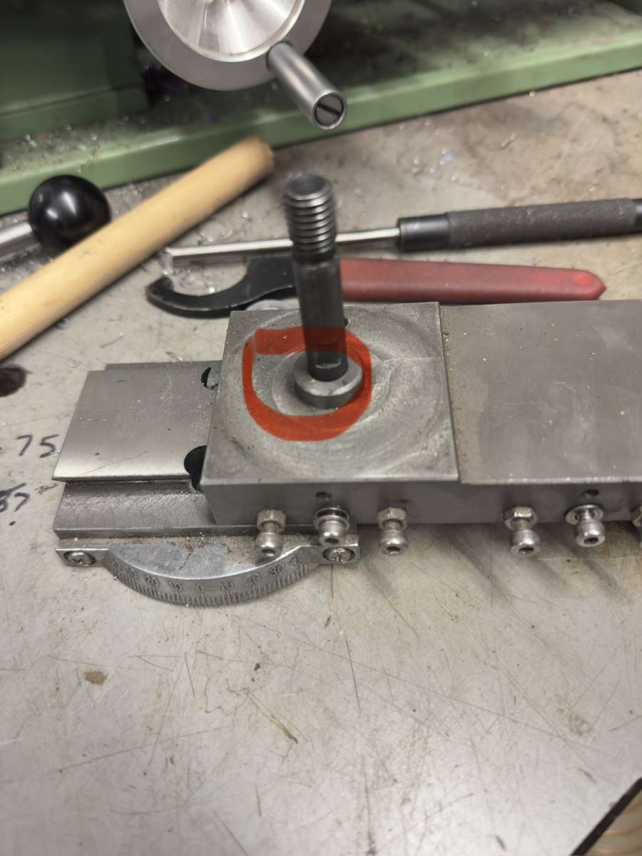
      Id like to make my wm180 a little more rigid, I know a lot of people remove the compound slide when adding a qctp for extra rigidity. I never use the CS so haven’t got a  problem with removing it, I would however like to keep the original 4 way tool post. I’ve got a lump of cast I could utilise to replace the CS but the spigot on top of the CS which the 4way sits on it is posing a problem, I’m struggling to find a way of incorporating it into the cast block? Any suggestions?

      thank you.

      #866294
      JasonB
      Moderator
        @jasonb

        I would have thought you could hold the block in the 4-jaw and turn a spigot on the end. At the same time drill the end for a suitable stud to take the toolposts nut.

        Alternative would be to put a bigger hole into the top of the block and incorporate the spigot as a larger diameter section of the stud

        A picture would help.

        #866297
        Andy Stopford
        Participant
          @andystopford50521

          Both Jason’s suggestions would work on the WM180. I would suggest going for the separate spigot idea since the fixed one is a nuisance if you did want to use a quick change toolpost at some stage.

          #866300
          Andy Brocklehurst
          Participant
            @andybrocklehurst85292
            On JasonB Said:

            I would have thought you could hold the block in the 4-jaw and turn a spigot on the end. At the same time drill the end for a suitable stud to take the toolposts nut.

            Alternative would be to put a bigger hole into the top of the block and incorporate the spigot as a larger diameter section of the stud

            A picture would help.IMG_2835


            #866301
            Journeyman
            Participant
              @journeyman

              Have a look here Journeyman’s Workshop has info on fitting 4-way toolpost to a WM250. Also includes a crossslide toolpost and mods for new mounting stud. There are a couple of pages I appreciate that the WM180 is a bit smaller but the ideas are the same. A quick glance may help with some ideas towards doing what you want.

              John

              #866304
              Andy Brocklehurst
              Participant
                @andybrocklehurst85292
                On Andy Stopford Said:

                Both Jason’s suggestions would work on the WM180. I would suggest going for the separate spigot idea since the fixed one is a nuisance if you did want to use a quick change toolpost at some stage.

                Thanks Andy, the only reason I’m keeping the 4 way is because I was given 4 of them. For what bit I do it’s not a big deal to change them and can’t warrant the cost of changing everything over.

                #866305
                Andy Brocklehurst
                Participant
                  @andybrocklehurst85292
                  On Journeyman Said:

                  Have a look here Journeyman’s Workshop has info on fitting 4-way toolpost to a WM250. Also includes a crossslide toolpost and mods for new mounting stud. There are a couple of pages I appreciate that the WM180 is a bit smaller but the ideas are the same. A quick glance may help with some ideas towards doing what you want.

                  John

                  Thanks John, that is helpful.

                  #866306
                  Phil S
                  Participant
                    @phils66830

                    Prior to this change might I suggest a little experiment. Attach a dial gauge indicator to the bed with the stylus vertical on the corner of the compound slide where the tool is usually positioned. Apply a downward load to the corner and note the deflection. Repeat with the stylus on top of the chuck again applying a downward load to the chuck. The first value should be very small, I get less than 2 microns. For the second I get 15 microns for an estimated 5-10 kg load. If your first value is not very small try with tighter gib settings. If things are in good order the weak point is the spindle stiffness rather than the slides.

                    Also worth applying an upward load to the chuck. Deflection should be similar to the downward, if more, the headstock bearings may need tightening. I found significant slack had developed with a few years use from new.


                    #866323
                    JasonB
                    Moderator
                      @jasonb

                      Having seen the picture both my previous suggestions still stand as it is how I thought it would be.

                      There is a third option which is to have a flat topped block so anything can be attached at a later date, plain shank to the stud and simply make a close fitting thick “washer” to slip over the plain shank of the stud and locates the recess in the toolpost so it can be spun round without sideways or front back movement. I think I would go with this option.

                      #866351
                      Andy Brocklehurst
                      Participant
                        @andybrocklehurst85292
                        On JasonB Said:

                        Having seen the picture both my previous suggestions still stand as it is how I thought it would be.

                        There is a third option which is to have a flat topped block so anything can be attached at a later date, plain shank to the stud and simply make a close fitting thick “washer” to slip over the plain shank of the stud and locates the recess in the toolpost so it can be spun round without sideways or front back movement. I think I would go with this option.

                        Thanks Jason,

                        Yes I like the sound of your third option.

                        #866358
                        Bo’sun
                        Participant
                          @bosun58570

                          Morning Andy,

                          Ade from “Ades Workshop” on YouTube did just this on his WM180, albeit with a home made QCTP.  Might be worth a look.

                          #866407
                          Clive Foster
                          Participant
                            @clivefoster55965

                            Interchangeable 4 way tool blocks preloaded with an appropriate selections of tooling in the way you are suggesting  are an effective alternative to quick change tool-post systems. I used that system for many years on SouthBend 9″ and Heavy 10 lathes finding it more than adequate for the jobs I did. My implementation lacked proper tool-post registration so it wasn’t as easy as I’d have ideally liked to put tool-posts back in the same place. This all began well before the days of affordable import QC systems.

                            With your proposed set-up it would be easy to arrange a suitable pin and hole system to give several repeatable positions. I designed but never built (due to swopping lathes for one with a Dickson QC system included) an improved version of mine featuring both pin and hole style location and a fast release system for the post holding “nut”.

                            I stole the castellated nut and tommy bar fast release concept from a device I’d used. For this job an externally threaded castellated sleeve nut screws into the tool-post to hold it down. The hold down “stud” is arranged so as to be able to rotate freely and cross drilled so a tommy bar sliding through the hole can engage in the castellated sleeve nut screwed into the tool-post. Clearly screwing the sleeve nut out of the tool-post using the tommy bar tensions the stud locking things up solidly. A part turn in the opposite direction releases the lock so the tommy bar can be withdrawn and the tool-post either lifted and rotated to another position so a different tool can be used or removed entirely to change for a post holding a different set of tools. The centre stud must be of sufficient diameter to be drilled for an adequately robust tommy bar without making it too weak around the hole.

                            Shimming tools to centre height is way easier with removable posts as it can be done on the bench by direct measurement. Shims do need to be kept sorted as to size. The colour coded plastic sheet shims make keeping things sorted easier although you have to allow for a slight squidge as the tool is bolted down. 10’s of a thou if I recall correctly.

                            Clive

                            #866435
                            Huub
                            Participant
                              @huub

                              If the compound slide is never used, tighten the gibs firmly for more rigidity.

                              I replaced my 4 way tool post for a self made qctp. Now I can swap tools in a second with excellent repeatability.

                              A video of the old version of my qctp. In the new version the top plate doesn’t need to rotate any more.

                              #866440
                              southernchap
                              Participant
                                @southernchap
                                On Phil S Said:

                                Prior to this change might I suggest a little experiment. Attach a dial gauge indicator to the bed with the stylus vertical on the corner of the compound slide where the tool is usually positioned. Apply a downward load to the corner and note the deflection. Repeat with the stylus on top of the chuck again applying a downward load to the chuck. The first value should be very small, I get less than 2 microns. For the second I get 15 microns for an estimated 5-10 kg load. If your first value is not very small try with tighter gib settings. If things are in good order the weak point is the spindle stiffness rather than the slides.

                                Also worth applying an upward load to the chuck. Deflection should be similar to the downward, if more, the headstock bearings may need tightening. I found significant slack had developed with a few years use from new.


                                It is always good to measure before making changes.  As you say, it may be found that changes are unnecessary, or that the problem is elsewhere.

                                One thing that I’d add would be for the OP to install an hss tool/carbide toolholder in one of their 4-ways with a typical stick-out and put the 4-way on their compound and apply pressure to the end of the tool, obviously while still keeping the DTI stylus contacting the compound.

                                The reason being is that in actual cutting, the tool acts as a lever arm, so just putting pressure on the compound seems to me to be unlikely to show the true level of deflection.

                                Can I ask what lathe did you do this experiment on?

                                #866456
                                Phil S
                                Participant
                                  @phils66830

                                  Can I ask what lathe did you do this experiment on?

                                  Southernchap, you are quite right the first test should be at the tool tip to be accurate. However on my WM180 it makes no difference with 10mm of tool and 10mm of compound projection.

                                  As far as I am aware the spindle at the front bearing is 30mm od with a 20-22 mm hole and the cutting point is at least 100-120mm out with a 3-4 jaw, thus I avoid heavy cuts that you could take on a bigger lathe.

                                  An alternative test might be to turn or part off a short stub of thick bar with and without some tailstock center support. If the extra support cuts chatter then the flex is at the spindle. (At risk of stating the obvious, best not part off completely with a centre in).

                                  #866616
                                  southernchap
                                  Participant
                                    @southernchap
                                    On Phil S Said:

                                    Can I ask what lathe did you do this experiment on?

                                    Southernchap, you are quite right the first test should be at the tool tip to be accurate. However on my WM180 it makes no difference with 10mm of tool and 10mm of compound projection.

                                    As far as I am aware the spindle at the front bearing is 30mm od with a 20-22 mm hole and the cutting point is at least 100-120mm out with a 3-4 jaw, thus I avoid heavy cuts that you could take on a bigger lathe.

                                    An alternative test might be to turn or part off a short stub of thick bar with and without some tailstock center support. If the extra support cuts chatter then the flex is at the spindle. (At risk of stating the obvious, best not part off completely with a centre in).

                                    Ooh, good idea about the no tailstock support/tailstock support.👍

                                  Viewing 16 posts - 1 through 16 (of 16 total)
                                  • Please log in to reply to this topic. Registering is free and easy using the links on the menu at the top of this page.

                                  Latest Replies

                                  Home › Forums › General Questions › Topics

                                  Viewing 25 topics - 1 through 25 (of 25 total)
                                  Viewing 25 topics - 1 through 25 (of 25 total)

                                  View full reply list.