Thanks Gentlemen
Your help has enabled me to proceed.
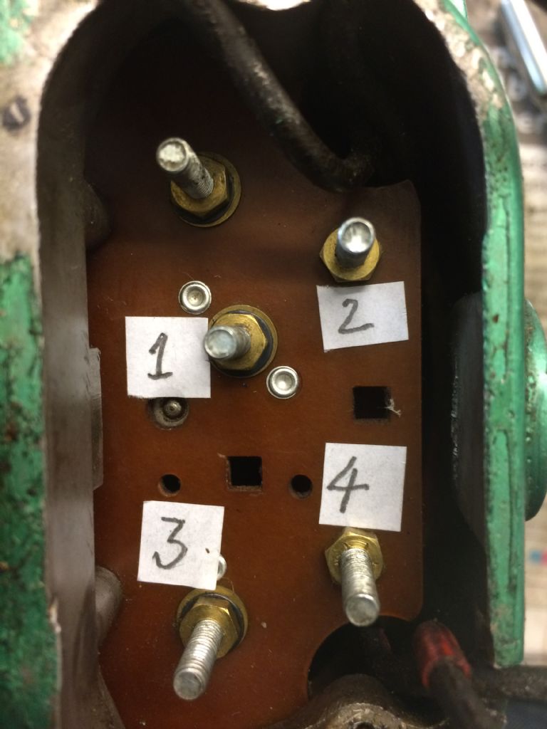
I started as Phil suggested by removing wiring and labeling the posts as per photograph below. As David mentioned, the removable link between posts 2 and 4 would not be required for reversing operation, so I took it out:

At this stage I didn't bother to number the top left post as I established it had no connection and therefore apparently no function.
I measured resistances between all the posts and discovered all were open circuit save for posts 1 to 3, which went closed circuit when the centrifugal switch was in the start position.
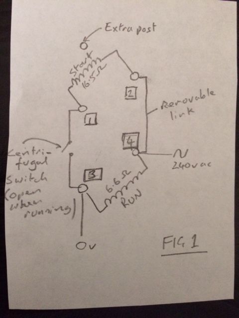
I measured the resistances between wires corresponding to posts in the starting position, and got 16.5 Ohms between 1 and 2, and 6.6 Ohms between 3 and 4. I know the resistance of the starter winding should be greater than the running winding, so 1 to 2 is the starter, and 3 to 4 is the running winding.
With this knowledge I was able to transcribe the circuit as Figure 1 below:

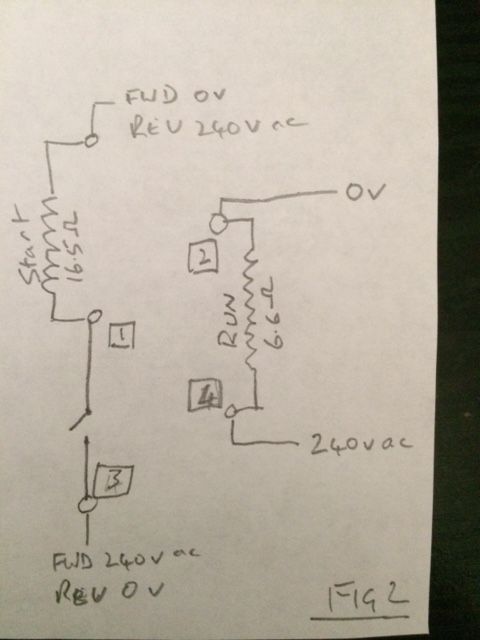
This is when I realised what the un-numbered post was for. I needed to be able to put the starting winding in series with the centrifugal switch. So, I rearranged the connections from the windings to the posts as per Figure 2 below:

To test this circuit, I lashed up a reversing switch arrangement using chocolate block connectors and tried it. It now works well and I can change the direction of the motor by reversing the polarity of the power connections at posts 1 and 3. Just need to wait for my reversing switch to arrive (I found one on eBay for about £9) and also the 4 core plus earth cable, then I can do the installation properly.
Thanks again to everyone for their help and support. I maybe could've worked it out by myself, but it would have taken quite a few days!
Cheers
Max
Max Francey.


