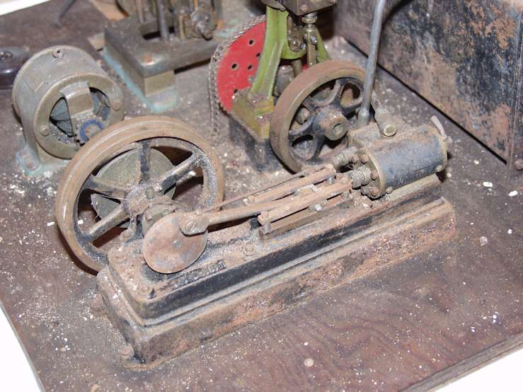
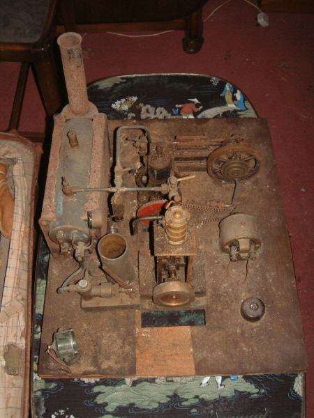
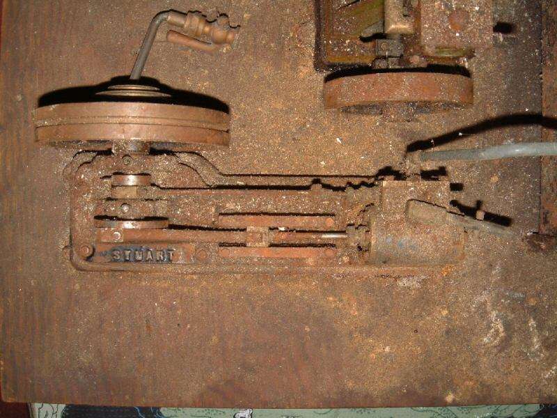
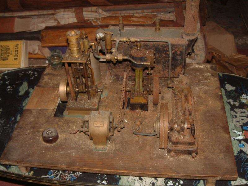
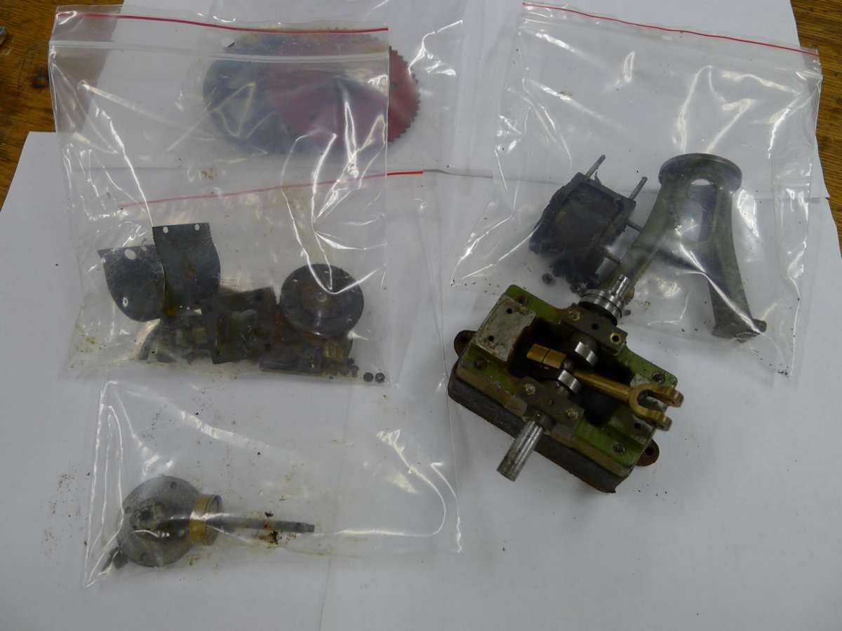
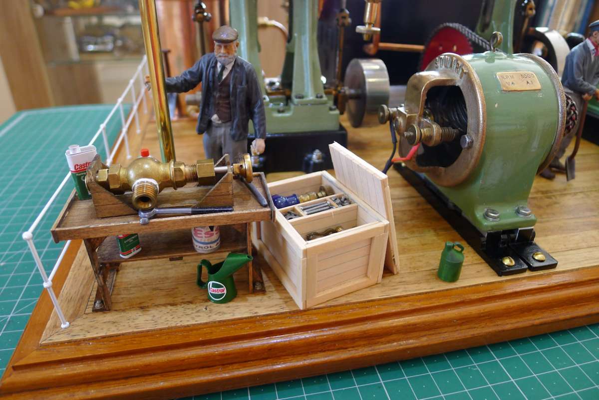
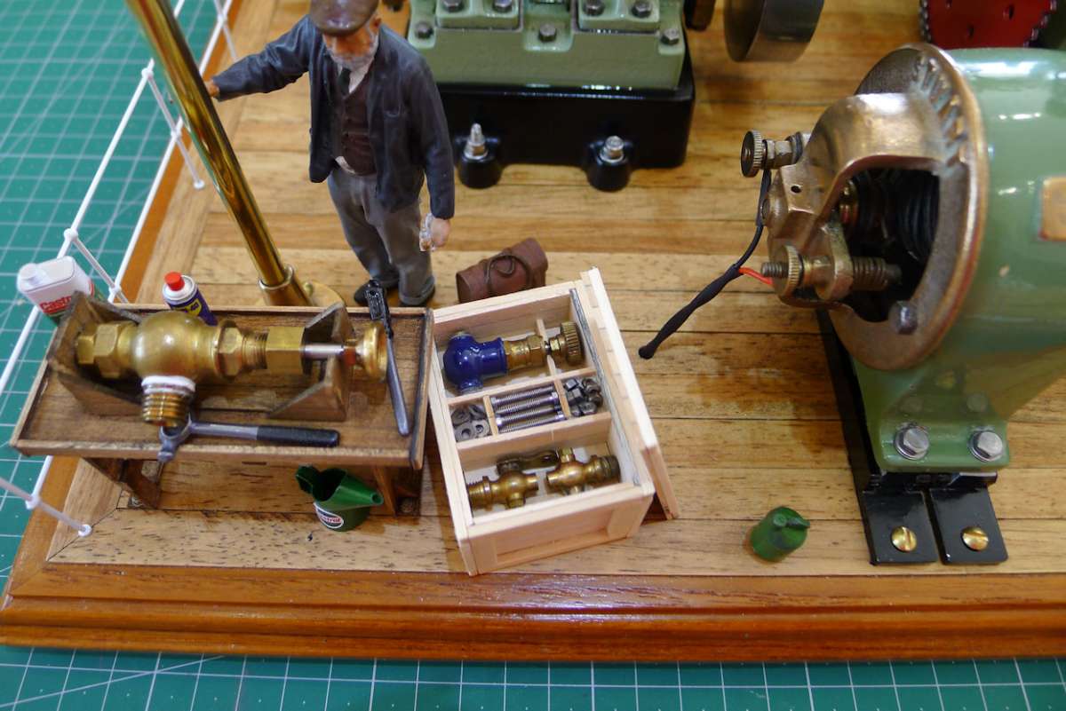
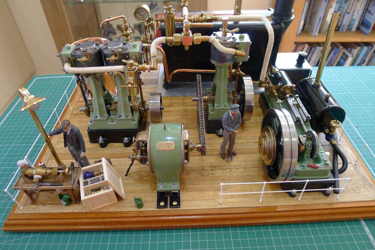
Stuart Restoration
Stuart Restoration
- This topic has 31 replies, 15 voices, and was last updated 11 August 2025 at 10:15 by
 parovoz.


- Please log in to reply to this topic. Registering is free and easy using the links on the menu at the top of this page.
Latest Replies
-
- Topic
- Voices
- Last Post
-
-
Odd RAF Specialist Tool?
Started by:
Martin King 2
in: Help and Assistance! (Offered or Wanted)
- 13
-
11 August 2025 at 11:24
Robert Atkinson 2
-
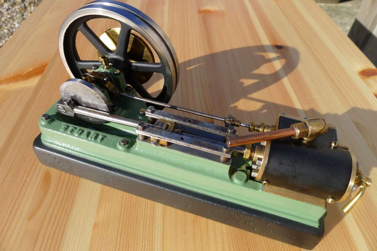
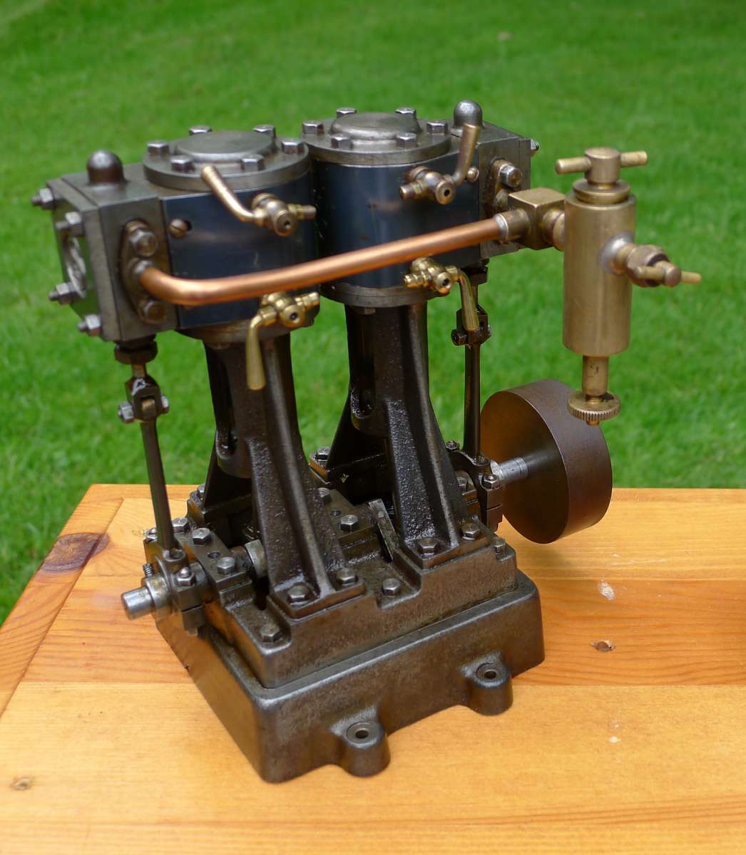
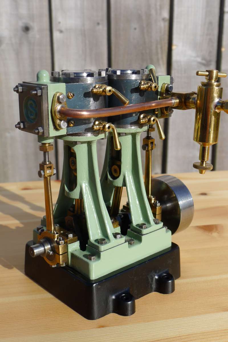
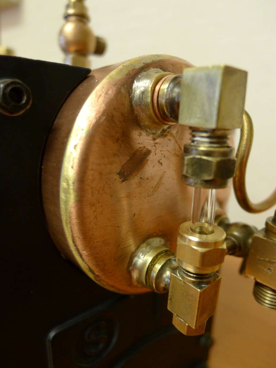
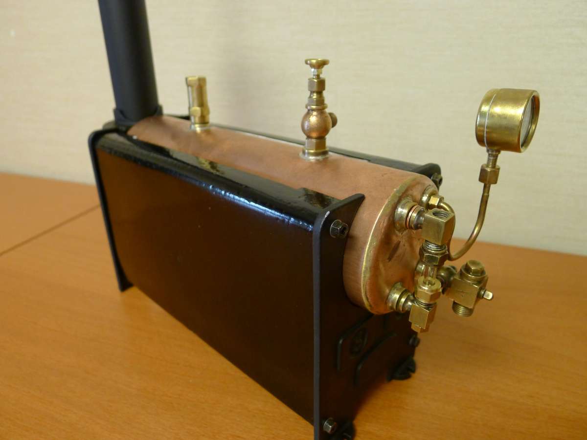
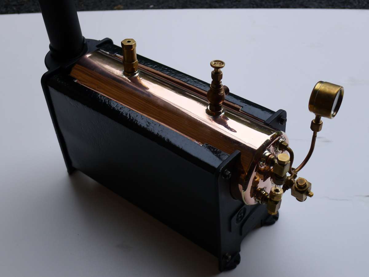
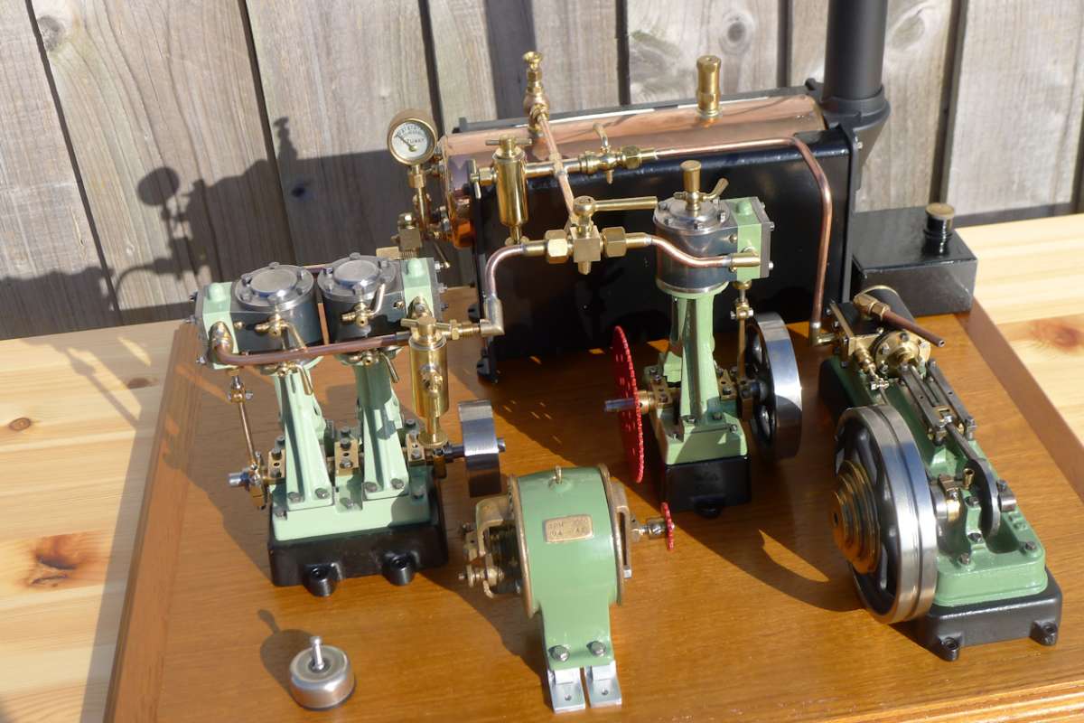
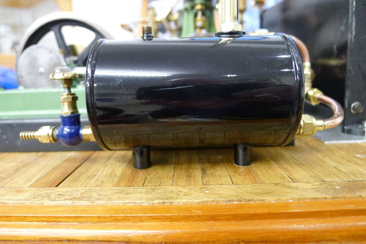
Stuart Restoration
1
2
Started by:
Richard Simpson
in: Stationary engines
- 15
-
11 August 2025 at 10:15
parovoz
-
Mini selfcentering stady rest
Started by:
dk0
in: Workshop Tools and Tooling
- 7
-
11 August 2025 at 10:12
dk0
-
Who’s to be trusted ?
Started by:
Michael Gilligan
in: Electronics in the Workshop
- 9
-
11 August 2025 at 09:48
Michael Gilligan
-
Where to buy Model Steam Engines
Started by:
David Deaville
in: General Questions
- 4
-
11 August 2025 at 09:32
MichaelR
-
Whats app
Started by:
duncan webster 1
in: The Tea Room
- 5
-
11 August 2025 at 09:31
Adrian R2
-
New Compressor
Started by:
Andy Brocklehurst
in: General Questions
- 14
-
11 August 2025 at 09:23
noel shelley
-
EW Stringer Lathe Spindle Thread
Started by:
James A
in: Workshop Tools and Tooling
- 8
-
11 August 2025 at 08:52
Martin of Wick
-
Thermal imaging
Started by:
John MC
in: The Tea Room
- 4
-
10 August 2025 at 21:17
Michael Gilligan
-
(help) hobymat md65 lathe z1 and z2 gears
Started by:
johnnyboy11
in: Workshop Tools and Tooling
- 5
-
10 August 2025 at 21:00
Bazyle
-
Which Carbide Lathe Tools?
1
2
Started by:
MarkS
in: Beginners questions
- 14
-
10 August 2025 at 20:44
old mart
-
Hex Wrench
Started by:
Vic
in: Workshop Tools and Tooling
- 8
-
10 August 2025 at 20:17
Clive Foster
-
Mill drill power feed
Started by:
Andy Sproule
in: General Questions
- 8
-
10 August 2025 at 20:07
old mart
-
Cheap Keyless Chuck on TEMU
Started by:
Chris Crew
in: The Tea Room
- 3
-
10 August 2025 at 19:14
Vic
-
Bandsaw vs Powered Hacksaw vs Chop Saw?
Started by:
MarkS
in: General Questions
- 19
-
10 August 2025 at 15:40
old fool
-
Superheaters
Started by:
Garry Coles
in: General Questions
- 9
-
10 August 2025 at 12:45
Dave Wootton
-
Being Nosey From Model Boats
Started by:
Richard Simpson
in: Introduce Yourself – New members start here!
- 4
-
10 August 2025 at 12:42
Howard Lewis
-
Presentazione
Started by:
dk0
in: Introduce Yourself – New members start here!
- 5
-
10 August 2025 at 12:40
Howard Lewis
-
Just How Many File Types Do We Need?
Started by:
Nigel Graham 2
in: The Tea Room
- 13
-
10 August 2025 at 11:28
John Haine
-
Cheap DRO
Started by:
Steve355
in: General Questions
- 3
-
10 August 2025 at 09:09
Steve355
-
BENCHMASTER SENIOR DONKEY SAW
Started by:
carcav13
in: Beginners questions
- 2
-
10 August 2025 at 07:16
Diogenes
-
My week this week! My workshop videos
1
2
…
11
12
Started by:
Phil Whitley
in: The Tea Room
- 15
-
10 August 2025 at 01:15
howardb
-
Help Wire 3 Phase 2 Speed Motor
1
2
Started by:
Allan Day
in: Electronics in the Workshop
- 16
-
10 August 2025 at 01:06
Wade Beatty
-
rotational motion into linear motion – force calculation?
Started by:
ell81
in: Beginners questions
- 9
-
9 August 2025 at 20:55
Martin Kyte
-
Odd Strain Gauge for Concrete?
Started by:
Martin King 2
in: Help and Assistance! (Offered or Wanted)
- 5
-
9 August 2025 at 20:09
V8Eng
-
Odd RAF Specialist Tool?


