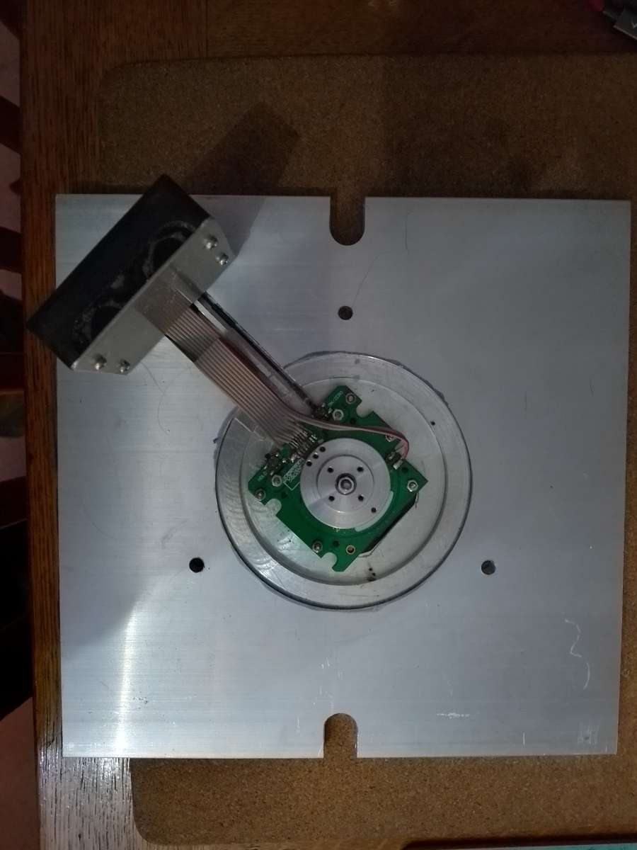
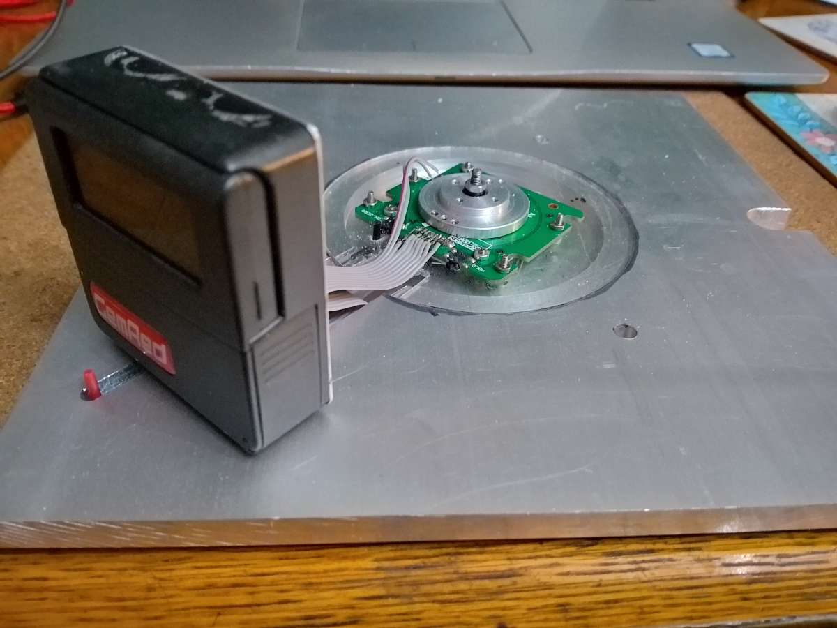
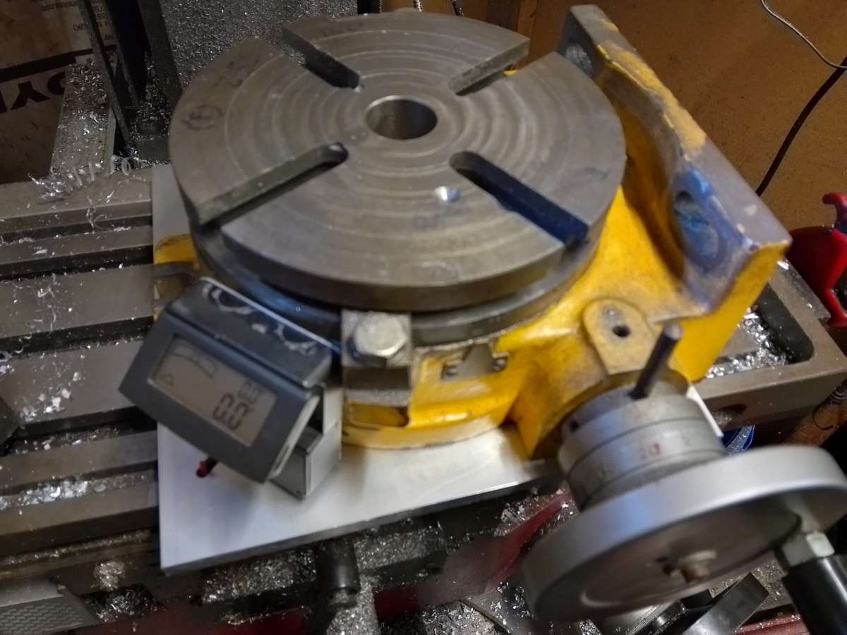
Rotary table digital readout
Rotary table digital readout
- This topic has 9 replies, 6 voices, and was last updated 8 March 2025 at 11:00 by
 petetwissell.


- Please log in to reply to this topic. Registering is free and easy using the links on the menu at the top of this page.
Latest Replies
-
- Topic
- Voices
- Last Post
-
-
wood working
Started by:
Danni Burns
in: Beginners questions
- 3
-
21 August 2025 at 22:58
Mark Easingwood
-
Blackgates 3 Way Toolpost Casting
Started by:
John McCulla
in: Materials
- 3
-
21 August 2025 at 22:48
Mark Easingwood
-
Solar panel
Started by:
duncan webster 1
in: Electronics in the Workshop
- 7
-
21 August 2025 at 22:30
duncan webster 1
-
Install & commission of a Chester Cub 630 (Warco GH750)
1
2
3
Started by:
Calum
in: Manual machine tools
- 22
-
21 August 2025 at 21:52
noel shelley
-
Asong power feed?
Started by:
Hollowpoint
in: General Questions
- 4
-
21 August 2025 at 21:43
andy198712
-
1″ Minnie Traction Engine
Started by:
milburyring@btinternet.com
in: Traction engines
- 3
-
21 August 2025 at 21:15
Andy Stopford
-
Softening epoxy
Started by:
John Haine
in: General Questions
- 17
-
21 August 2025 at 18:57
Martin Dilly 2
-
Granville lathe leadscrew change wheel
Started by:
JACK SIDEBOTHAM
in: Help and Assistance! (Offered or Wanted)
- 9
-
21 August 2025 at 18:43
John Hinkley
-
The stand alone weight for tower clock
1
2
Started by:
dk0
in: Clocks and Scientific Instruments
- 12
-
21 August 2025 at 17:52
dk0
-
What Did You Do Today 2025
1
2
…
9
10
Started by:
JasonB
in: The Tea Room
- 35
-
21 August 2025 at 17:38
Dalboy
-
Denford Orac refit
Started by:
Richard Evans 2
in: CNC machines, Home builds, Conversions, ELS, automation, software, etc tools
- 3
-
21 August 2025 at 14:56
Richard Evans 2
-
Phone Phreaking
Started by:
Michael Gilligan
in: Clocks and Scientific Instruments
- 10
-
21 August 2025 at 12:48
Clive Steer
-
F360 stock from solid
Started by:
Roderick Jenkins
in: CNC machines, Home builds, Conversions, ELS, automation, software, etc tools
- 9
-
21 August 2025 at 10:44
Roderick Jenkins
-
Harold Hall – 1933 -2024
Started by:
Neil Wyatt
in: Website Announcements
- 14
-
21 August 2025 at 00:07
Michael Gilligan
-
Manual for Warco GH750 or Chester Cub 630
Started by:
Gavlar
in: General Questions
- 7
-
20 August 2025 at 22:54
peagreenpete
-
Greatest Model Engineer
Started by:
Juddy
in: The Tea Room
- 17
-
20 August 2025 at 21:41
Nigel Graham 2
-
Material advice
Started by:
tobyonekenobi
in: Materials
- 4
-
20 August 2025 at 20:34
tobyonekenobi
-
Cheap DRO
Started by:
Steve355
in: General Questions
- 11
-
20 August 2025 at 20:22
bernard towers
-
Drain Cock search
Started by:
Speedy Builder5
in: Locomotives
- 3
-
20 August 2025 at 20:20
bernard towers
-
Raab Style Heibluftmotor
Started by:
JasonB
in: Miscellaneous models
- 3
-
20 August 2025 at 18:50
JasonB
-
Reference lines for dimensions – Fusion 360
Started by:
John McCulla
in: CAD – Technical drawing & design
- 5
-
20 August 2025 at 14:39
blowlamp
-
Use of Hydrostatic lubrication in steam locomotives
Started by:
Greensands
in: Locomotives
- 6
-
20 August 2025 at 14:13
Dave Wootton
-
Opposed Piston Engines
1
2
Started by:
Richard Simpson
in: The Tea Room
- 13
-
20 August 2025 at 09:42
Howard Lewis
-
Making Unimat DB/SL Steadies
1
2
Started by:
Andy Carlson
in: Workshop Techniques
- 12
-
20 August 2025 at 09:25
Michael Gilligan
-
Steam driven air pump for brakes
Started by:
Werner Schleidt
in: Locomotives
- 10
-
20 August 2025 at 08:05
Werner Schleidt
-
wood working


