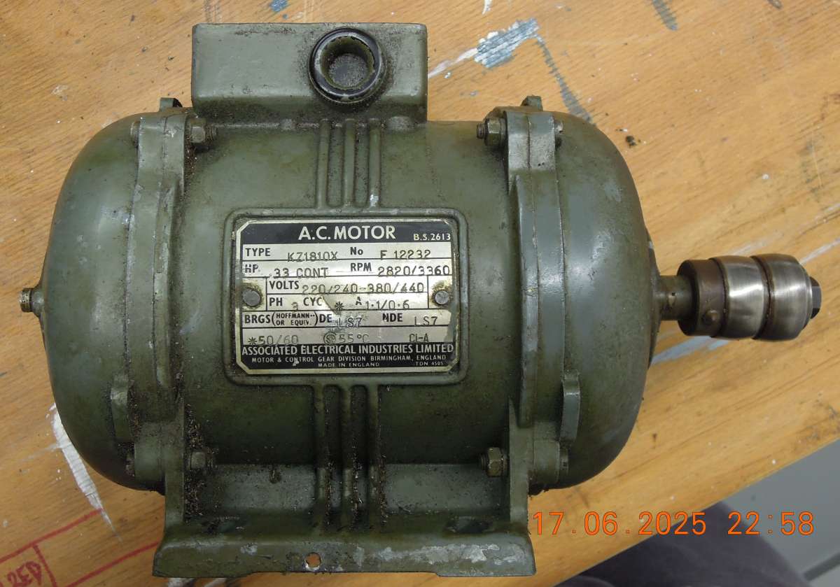
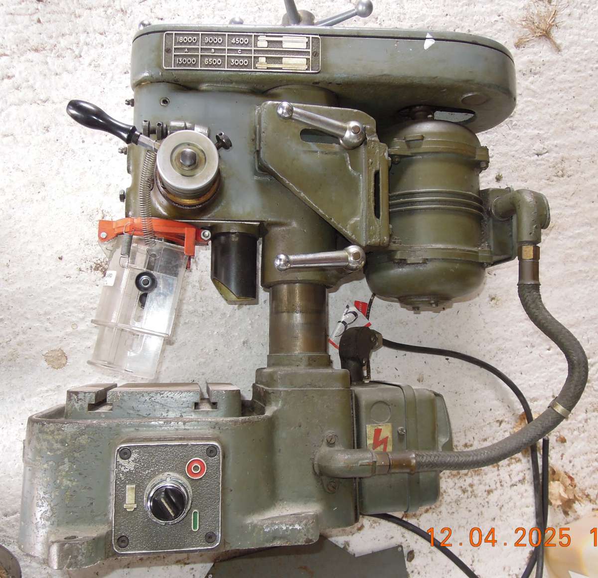
Pulley taper – Herbert B drill
Pulley taper – Herbert B drill
- This topic has 19 replies, 8 voices, and was last updated 27 June 2025 at 10:36 by
 SillyOldDuffer.

- Please log in to reply to this topic. Registering is free and easy using the links on the menu at the top of this page.
Latest Replies
-
- Topic
- Voices
- Last Post
-
-
Quartz clock movement
Started by:
duncan webster 1
in: Electronics in the Workshop
- 2
-
24 August 2025 at 23:55
duncan webster 1
-
Phone Phreaking
Started by:
Michael Gilligan
in: Clocks and Scientific Instruments
- 11
-
24 August 2025 at 23:20
Chris Crew
-
Milling for beginners book, Where?
Started by:
andy198712
in: Beginners questions
- 8
-
24 August 2025 at 22:48
Mark Easingwood
-
Bending copper tube?
Started by:
Bo’sun
in: Workshop Techniques
- 7
-
24 August 2025 at 22:17
Macolm
-
Lathe tool inserts
Started by:
Andy Brocklehurst
in: Beginners questions
- 3
-
24 August 2025 at 22:13
Andy Brocklehurst
-
Recommendations for book on clock repairs
Started by:
Andy Stopford
in: Clocks and Scientific Instruments
- 4
-
24 August 2025 at 21:40
Brian Merrifield
-
THE MAUDSLAY TABELE ENGINE
Started by:
sivtek1
in: Stationary engines
- 4
-
24 August 2025 at 20:27
Michael Gilligan
-
Progress no.1 restoration
Started by:
flyingsailor
in: Workshop Tools and Tooling
- 9
-
24 August 2025 at 19:52
duncan webster 1
-
A4 stainless
Started by:
David Ambrose
in: Materials
- 14
-
24 August 2025 at 19:15
old mart
-
Blackgates 3 Way Toolpost Casting
Started by:
John McCulla
in: Materials
- 13
-
24 August 2025 at 19:00
duncan webster 1
-
Softening epoxy
1
2
Started by:
John Haine
in: General Questions
- 18
-
24 August 2025 at 18:59
old mart
-
Joined 24 August 2025
Started by:
simon912
in: Introduce Yourself – New members start here!
- 3
-
24 August 2025 at 18:59
noel shelley
-
The stand alone weight for tower clock
1
2
Started by:
dk0
in: Clocks and Scientific Instruments
- 12
-
24 August 2025 at 18:33
bernard towers
-
Denford Orac refit
Started by:
Richard Evans 2
in: CNC machines, Home builds, Conversions, ELS, automation, software, etc tools
- 3
-
24 August 2025 at 16:59
Richard Evans 2
-
Manual for Warco GH750 or Chester Cub 630
Started by:
Gavlar
in: General Questions
- 7
-
24 August 2025 at 16:03
Gavlar
-
THE MAUDSLAY TABELE ENGINE
Started by:
sivtek1
in: Introduce Yourself – New members start here!
- 2
-
24 August 2025 at 11:57
sivtek1
-
CNC Coolant
1
2
3
Started by:
Steve355
in: CNC machines, Home builds, Conversions, ELS, automation, software, etc tools
- 13
-
24 August 2025 at 11:37
Steve355
-
QCTP for chester lathe
1
2
Started by:
Chris12
in: Beginners questions
- 11
-
24 August 2025 at 11:11
dk0
-
Material advice
Started by:
tobyonekenobi
in: Materials
- 10
-
24 August 2025 at 10:57
tobyonekenobi
-
Model Aircraft Engine
Started by:
Alan Charleston
in: Suggested Online Resources
- 2
-
24 August 2025 at 09:38
Michael Gilligan
-
Smart & Brown Model L lathe help required
Started by:
AJAX
in: Manual machine tools
- 1
-
23 August 2025 at 21:45
AJAX
-
This weeks oddity!
Started by:
Martin King 2
in: Help and Assistance! (Offered or Wanted)
- 4
-
23 August 2025 at 17:29
Martin King 2
-
Asong power feed?
Started by:
Hollowpoint
in: General Questions
- 5
-
23 August 2025 at 16:55
Stuart Smith 5
-
New member, progress no.1 rest
Started by:
flyingsailor
in: Introduce Yourself – New members start here!
- 5
-
23 August 2025 at 16:11
flyingsailor
-
My week this week! My workshop videos
1
2
…
11
12
Started by:
Phil Whitley
in: The Tea Room
- 16
-
23 August 2025 at 16:05
Phil Whitley
-
Quartz clock movement


