New Rotary Table question

Advert

New Rotary Table question

Home Forums Beginners questions New Rotary Table question

Viewing 25 posts - 26 through 50 (of 50 total)
  • Author
    Posts
  • #722707
    Chris Mate
    Participant
      @chrismate31303

      Ok, I facemilled the underside, find the centre, dril a gole to slipfit the MT-2 shank, and bored a pocket to slipfit the top 3mm protroding of the MT2 above table.
      Now I have to decide what to do with the MT2 shank sticking out on top, maybe tread it with nut + a very short drawbar make to screw into the MT2 from the bottom.

      Plus using the 3-T-Slots on top to clamp the Disc to the table, and then facemill the top flat on the table+ round circumference of disc, then decide to drill holes for clamps.

      So the disc locate to MT-2 top as well as shank, and shank can be used to locate the whole setup to mill spindle.

      See photos:


      Advert
      #722720
      JasonB
      Moderator
        @jasonb

        It can be quite useful to have a spigot sticking up out the middle to locate work on but not when you want to mount something flat. If it were me I would face or mill the end of the spigot so it sits just below your aluminium table.

        Then drill and ream 6mm or 1/4″ if you are that way inclined and carry the hole down and tap M4. That gives you the option of making up some stepped spigots to locate holes as well as being able to bolt parts down using the same central hole. Upto you if you want a single long 6mm spigot and rings to fit it or make a series of stepped ones that are 6mm one end and say 8, 10, 12 etc the other.

        The thread can also be used to pull  the MT from the table if needed.

        #722730
        Chris Mate
        Participant
          @chrismate31303

          Thanks, I like 6-8-10-12….idea, so will mill it down. I have 9.2mm to work with, so 6mm will work.

          #724007
          Chris Mate
          Participant
            @chrismate31303

            Just another quick question. I would like to believe the RT is accurate, however if I line up the groves(1-2-3) with the X-Axis after centered on both(X+Y)(Like a double check), I don’t get result as I would expected.

            Start from 0: Then on to 93 degrees for nr-1……

            The results I got was:One would expect the difference to be 120 degrees-?
            1=    93 – 1 – 30

            ————————DIff=118-59-0

            2=  212 – 0 – 30

            ————————DIFF=121-0-5

            3=  333 – 1 – 5

            So my question is , would plates be more reliable than using the degree-minute-seconds option to rotate-?

            #724023
            Pete
            Participant
              @pete41194

              Yes the plates for doing divisions will almost for sure be much more accurate than depending on the dial and vernier scale. Less chance of making counting errors as well for odd numbers of degrees and minutes. Inaccuracy’s in the exact placement of those holes in the dividing plates are less important than it might seem. In use, any errors in those plates are divided by the worm and worm wheel ratio. Most of the smaller rotary tables I know of are 90-1. If those accessory plates, sector fingers and other extras are available as a direct bolt on item for your rotary table, I think there well worth having.

              I’d suggest if your tee slot spacing is that poorly done, I’d also check your table flatness and run out on the tables Morse Taper. For most work it may not matter, but better to know what amount there is if or when your trying to use it with a Morse Taper stub arbor to center the table to the mill spindle. Rotate the table a full revolution with the probe end of a dti at various radii on the table and then inside that taper. Any run out in that MT, then write the degree number down from those degree markings on the side of the table and how much it is for future reference. My Vertex table had almost .0004″ run out when new. And both that and the actual table flatness numbers certainly didn’t match what it’s “certificate of accuracy” numbers were.


              #724025
              Howard Lewis
              Participant
                @howardlewis46836

                My HV6 is most often used for gear cutting, so Division Plates are always used.

                Personally. I have nevr bothered about lining up a slot withe mill table.

                If you do, and then disengage the worm from the wormwheel, the table can “freewheel” so that the ooriginal 0 – 0 -0 settings no longer apply.

                If, with the worm engaged properly, the table is set, accurately to Zero, the graduated ring on the handwheel can be repositioned, so the Zero coincides with the Zero on the Vernier scale.

                Basic checks should show :

                Startying with everything set at Zero, 40 complete turns with the handwheel and Zero marks aligned, the table should read 90.

                Again from all Zeros, 90 complete turns should result in everything returning to Zero.

                So from 0-0-0, 40 turns should produce 0 – 0 – 90; 90 turns from 0 – 0 – 0 should result in readings of

                0 – 0 – 0 again.

                Have you found this?

                Howard

                #724028
                JasonB
                Moderator
                  @jasonb

                  When you say “Grooves 1-2-3″ do you mean the tee slots? I would not expect them to be particularly accurate and they are the only thing I can think of that may be at 120deg spacing. And yes most tables don’t have the zero in line with any of the tee slots (Sieg ones excepted)

                  #724103
                  Howard Lewis
                  Participant
                    @howardlewis46836

                    Why is it necessary to align the T slots on the HV6 with the T slots on the mill table?

                    In well over twenty years of use, I have never found the need.

                    The relationship is unlikely to be exact because of backlash, unless the direction of rotation is always the same.

                    As Jason says, the slots, only intended for clamping, are unlikely to be machined as precisely as the components in the rest of the table

                    If the worm is ever disengaged from the wormwheel, the relationship, between the dial graduations and the slot is lost anyway.

                    The purpose of the table is to allow work to be rotated by a precise angle, so wherever the work is clamped to the table the cut can be taken at the required angle from the datum, or the previous cut.

                    Howard

                    #724138
                    Nicholas Farr
                    Participant
                      @nicholasfarr14254
                      On Howard Lewis Said:

                      My HV6 is most often used for gear cutting, so Division Plates are always used.

                      Personally. I have nevr bothered about lining up a slot withe mill table.

                      If you do, and then disengage the worm from the wormwheel, the table can “freewheel” so that the ooriginal 0 – 0 -0 settings no longer apply.

                      If, with the worm engaged properly, the table is set, accurately to Zero, the graduated ring on the handwheel can be repositioned, so the Zero coincides with the Zero on the Vernier scale.

                      Basic checks should show :

                      Startying with everything set at Zero, 40 complete turns with the handwheel and Zero marks aligned, the table should read 90.

                      Again from all Zeros, 90 complete turns should result in everything returning to Zero.

                      So from 0-0-0, 40 turns should produce 0 – 0 – 90; 90 turns from 0 – 0 – 0 should result in readings of

                      0 – 0 – 0 again.

                      Have you found this?

                      Howard

                      Hi Howard, I might be missing something here, but as the HV6 turns the table 4 degrees for every single turn of the handwheel, and starting with everything set at zero, 40 X 4 = 160, 90/4 = 22.5 turns of the handwheel.

                      Regards Nick.

                      #724175
                      Chris Mate
                      Participant
                        @chrismate31303


                        1-Why is it necessary to align the T slots on the HV6 with the T slots on the mill table?
                        2-The zero=No it does not matter, but the T-Slots are spaced and I need to know that.

                        Hi, I use this to line up and drill 2x holes through aluminium disc per t-Slot, to bolt it down to rotary table to the 3x T-Slots.
                        I ordered a MT2 arbour with facemill parts & threaded hole with bolt=If this is useable, I will fit the DISC over that into/onto the Rotary Table.

                        #724189
                        Howard Lewis
                        Participant
                          @howardlewis46836

                          Nick,

                          Quite right!.

                          Brain not working well in the rsmall hours, (Couldn’t sleep) but you understand what was mean as a check.

                          The main thing will be to drill the holes through the plate without damaging the HV6 table. I would not have thiught that it would matter greatly if the T slots were a degree or two out, since the plate will be secured by studs and T nuts, which will not be reamed fits.

                          STILL cannot understand the need to align a T slot on the HV6 with one on the mill table. Obviously do not know what you are trying to achieve.

                          You can buy a 2MT arbor with a Myford thread if you wish to mount work in a chuck (3 or 4 jaw) on the HV6. Mine has a M6 thread so needed a small top hat bush for a capscrew to secure it in the RT.

                          (Used with suitable sleeves in the big lathe for turning the blank, before transferring to the HV6 to cut the gear, and maintaining concentricity)

                          Alternatively, a 2MT blank arbor could be modified to carry the disc (Central hole to clamp and two small rollpins to ensure location).  To make the OD concentric, mount the assembly in the lathe and skim the OD to just clean up.

                          There can be just enough clearance under the disc for the drill point not to mark the HV6 table. If need be put a bit of sacrificial hardboard under before drilling.

                          Howard


                          #724224
                          Chris Mate
                          Participant
                            @chrismate31303

                            “STILL cannot understand the need to align a T slot on the HV6 with one on the mill table. Obviously do not know what you are trying to achieve.”

                            Hi the only way I can drill through the disc and not damaging the table is:The slow way:
                            1-To check alignment by moving the X-Axis…spindle with spot dril.
                            2-To align the RT T-Slot with the movement of the X-Spindle through its lenght, so spindle moves along mill & RT X-axis together, no misalignment.
                            3-To chose spot of 1st hole looking at thr RT T-slot centre, lock it there.
                            4-Lift spindle up.
                            5a-Insert disc…..Mark the spot hole 1(1-1)
                            5b-Remove disc.
                            5c-Let spindle down…position spindle for hole 2 in centre of RT T-Slot.
                            5d-Lift spindle up.
                            5e-Insert disc…..Mark the spot hole 2(1-2)
                            6 – After holes drilled on drillpress, insert long T-nut in RT T-Slot.
                            7 – Mark the holes on the long T-Nut, drill and thread 8mm.
                            8 – Then chose correct lenght bolts, install disc, see if its ok.
                            9 – Then remove disc, and repeat the process for (2-1)(2-2 & (3-1)(3-2) bolt holes.
                            10-I feel this slow way I can position the bolts in slots pretty good, time is not a problem for me, and I don’t trust the degree thing enough(Seconds ignored).

                            I hope this explains why.


                            #724232
                            JasonB
                            Moderator
                              @jasonb

                              Why do you need to drill it when on the table.

                              Zero your DRO or handwheels over the ctr of the rotary table, have table so it’s handwheel and scale notch are 0,0,0

                              Hold a bit of say 10mm bar in a collet. Or whatever diameter is a close fit between slots for  an even more accurate job.

                              Lower the quill in six places (2 x 3) along the slots and note the DRO reading when the bar fits nicely between the slots.

                              You can then clamp the plate to the mill table on suitable spacers, locate it’s ctr and again zero handwheels or DRO.

                              Now go round to the size co-ordinates that you recorded and spot, drill, CSK or Counterbore and job is done with no risk to the table or drill bits.

                              You can also add your chosen hole pattern at the same DRO setting.

                              The modern term for this would be “probing” but you are just using a bit of bar rather than an expensive probe.

                              #724239
                              JasonB
                              Moderator
                                @jasonb

                                Regarding your initial 93- 1 -30 deg reading. If you simply loosen the handwheel dial and rotate that until it reads zero your numbers are then a lot closer. When the scale then reads 0-0-0 the slot will be lined up with Y as the maker intended. The only way it will read 0-0-0 in the x alignment is with a new marker 90deg from the first.


                                If you really want one slot to line up with X axis rather than the makers choice of Y then wind the table round until your chosen slot lines up left or right with X.

                                Loosen the handwheel dial and adjust that to zero

                                Mark the side of the table’s base casting where the zero position is on the 360deg scale

                                Make a new marker plate and fit to the table where you made your mark

                                #724262
                                Clive Foster
                                Participant
                                  @clivefoster55965

                                  Picking up on the tapped hole plate suggestion from Bazyle maybe consider getting one of the solid aluminium breadboards from optical equipment suppliers such as Thor Labs  https://www.thorlabs.com/newgrouppage9.cfm?objectgroup_id=159&pn=MB6x . At £50 ish plus tax for a 6″ square the price isn’t totally out of order and you get a nice grid of accurately located holes. Double density pattern is more versatile but twice the price.

                                  I find that for small jobs a simple slotted bar with one end bent down to give an L shape is both easier to fit in and adequately stiff in 3 or 4 mm steel. Quick, easy and cheap to make as needed so I’ve no compunctions about simply slicing through one that is in the way as a job comes to an end avoiding the clamp dance to get a more costly purchased one out of the way whilst hoping the job hasn’t shifted. 6 mm thick light alloy bar fingers with a slot for the hold down bolt and tapped hole at the other end for a jacking screw work well too with grid of hole tables. Just remember to either fix a foot on to the screw to avoid damaging the table or slip a hard washer under the end.

                                  Given the similarity in price between one of the common import clamp sets and a Thor Labs 1/2″ breadboard I reckon the breadboard and home made clamps is most likely a better fit than a purchased clamp set for ME size work.

                                  Clive

                                  #724327
                                  Howard Lewis
                                  Participant
                                    @howardlewis46836

                                    Chris, my earlier post suggested means of preventing damage to the RT.

                                    There can be just enough clearance under the disc for the drill point not to mark the HV6 table. If need be put a bit of sacrificial hardboard under before drilling.”

                                    Being bone idle, I always look for the easist way out!

                                    Howard


                                    #724418
                                    Peter Cook 6
                                    Participant
                                      @petercook6
                                      On Clive Foster Said:

                                      6 mm thick light alloy bar fingers with a slot for the hold down bolt and tapped hole at the other end for a jacking screw work well too with grid of hole tables. Just remember to either fix a foot on to the screw to avoid damaging the table or slip a hard washer under the end.

                                      I find that a coach bolt makes a good quick and simple jacking screw. Nice smooth head against the table, and a convenient square for minor adjustments just above it.

                                      #724446
                                      Clive Foster
                                      Participant
                                        @clivefoster55965
                                        On Peter Cook 6 Said:
                                        On Clive Foster Said:

                                        6 mm thick light alloy bar fingers with a slot for the hold down bolt and tapped hole at the other end for a jacking screw work well too with grid of hole tables. Just remember to either fix a foot on to the screw to avoid damaging the table or slip a hard washer under the end.

                                        I find that a coach bolt makes a good quick and simple jacking screw. Nice smooth head against the table, and a convenient square for minor adjustments just above it.

                                        Most excellent idea Peter.

                                        Been playing around with grid of hole tables for something approaching 40 years and it never occurred to me. Would have made a few things much easier.

                                        Guess its hard to fix stupid.

                                        Clive

                                        #724462
                                        Pete
                                        Participant
                                          @pete41194

                                          Copper pennies were discontinued here a few years ago. So I use them as table protectors under any jacking screws. Even if I could use them at there face value, there a lot cheaper than buying any large enough washer.

                                          #724510
                                          Chris Mate
                                          Participant
                                            @chrismate31303

                                            On JasonB Said:

                                            Reply:

                                            ……………Note:I do not have  a DRO, I probably operates pre-1900’s……….Slow going

                                            Why do you need to drill it when on the table.
                                            Answer:I am never going to drill the disc while on the table ever, just marking it/spot dril, the repeating process.

                                            Zero your DRO or handwheels over the ctr of the rotary table, have table so it’s handwheel and scale notch are 0,0,0
                                            Answer=No DRO.

                                            Hold a bit of say 10mm bar in a collet. Or whatever diameter is a close fit between slots for  an even more accurate job.

                                            Answer:Yes a 11mm dril fit snug in groove, so I drilled a centre mark in cut off piece of drill, and aim the Wiggler centred on it. Then I wind the X-Axis to see how it align to the slot.

                                            Lower the quill in six places (2 x 3) along the slots and note the DRO reading when the bar fits nicely between the slots.
                                            Answer=No DRO….This makes it slow, I have to do it slot by slot with reference to 1st slot bolted.

                                            You can then clamp the plate to the mill table on suitable spacers, locate it’s ctr and again zero handwheels or DRO.
                                            Answer=Yes bolt on spacers to mill table or Drill Press and drill the marked(Spotted) points. Then hope it fits perfectly to the table bolted to T-Slots/Tnuts.

                                            Now go round to the size co-ordinates that you recorded and spot, drill, CSK or Counterbore and job is done with no risk to the table or drill bits.

                                            You can also add your chosen hole pattern at the same DRO setting.

                                            The modern term for this would be “probing” but you are just using a bit of bar rather than an expensive probe.
                                            Answer=Yes basicly this is similar to what I am going to end up doing with Mill or Drillpress.

                                            —-

                                            Note:I am just waiting for a MT2 arbor threaded at bottom(For drawbar, which will be the shortest one on the planet to pull the MT2 fast to table and keep it there). The arbor has a precision grinded round surface and in the centre a threaded hole plus a locknut and more=I will see how I can make this work, and that will be the new locating point for the RT+Disc when finished.

                                            —-

                                            Note:After that I never have to worry about the T-Slots again. I can now probably mount a larger chuck as well. 150mm RT=160mm plus chuck bolted to disc.

                                            I do appreciate all the feedback, thanks.


                                            #724960
                                            Chris Mate
                                            Participant
                                              @chrismate31303

                                              Ok, I received MT2 shank (for Facemill) to use and fit Disc:

                                              Step 1:Drill hole

                                              Step 2: Bore small hole for MT2 tip.

                                              Step 3:Fit MT2 to Disc

                                              Step 4: Bore large hole for MT2 base and fit.

                                              Step 5: Fit & bolt MT2 to Rotary Table, then fit Disc over MT2 on Rotary Table.
                                              This is where I am now with the 3x T-Nuts to pull the DISC down on Rotary Table.

                                              End of this part.


                                              #724981
                                              Pete
                                              Participant
                                                @pete41194

                                                On mine I machined a steel bushing with a thick flange for the bottom of the table. The upper part of that bushing fit’s inside the bore of the R/T’s spindle for a short distance to keep it concentric, and it was counter bored to use an Allen head cap screw for Morse Taper shanks. Basically it looks like an inverted top hat shape. There’s not much space left between the end of the R/T’s spindle and the table base when the table is used horizontally. So that was the easiest design I thought would still be durable enough that I could think of.

                                                #724985
                                                Clive Foster
                                                Participant
                                                  @clivefoster55965

                                                  +1 for Davids extended Tee nuts with extra holes. Several came with my first milling machine, a BCA, and they ere very useful in extending the useful working area of what is small machine. (The BCA has built in rotary table so the available space is rather less than on a conventional mill.)

                                                  After resorting working with the Tee nuts sticking outside the table so I had something to support the clamp jack screws on I figured it was time to get a bigger machine more suited to what I actually ended up doing.

                                                  Clive

                                                  #725377
                                                  Chris Mate
                                                  Participant
                                                    @chrismate31303

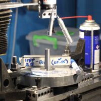
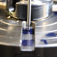
                                                    Ok, I finished drilling holes 8mm, sink bolt head down in Disc with 12mm end mill.

                                                    1-Set up RT on mill table centre X/Y axis. Lock Y-Axis down,
                                                    2-Rotate table with NR1 slot in line with X-axis.
                                                    3-Use wiggler and rotate RT to centre of slot using wiggler, a centerline was scraped on T-Nut snug fitting to indicate centre of t-Slot(Good enough for this).
                                                    4-Lock RT down with its own clamps.
                                                    5-Make use of Mill table X-Axis locknuts(Set limits) to only move X-Axis between points NR1 (A) & NR1 (B) using wiggler.
                                                    6-Now I can go backwards and forward and step up drilling holes till 8mm.
                                                    7-Determine lenght of 8mm Allen Key bolts through T-Nut(Clearance at bottom)
                                                    8-Turn Allen key bolt heads down on lathe to 11.85mm to fit 12mm hole.
                                                    9-Bolt Disc down to RT…..Finished with Nr 1 A & B.
                                                    10-To be repeated for other two T-Slots.

                                                    See photos:

                                                    NR1 A


                                                    NR1 B


                                                    NR1 A & B Finished


                                                    #726446
                                                    Chris Mate
                                                    Participant
                                                      @chrismate31303

                                                      Finished the T-Slots to Disc with 8mm bolts.

                                                      1-Milled circumference of disc round from centre with RT.

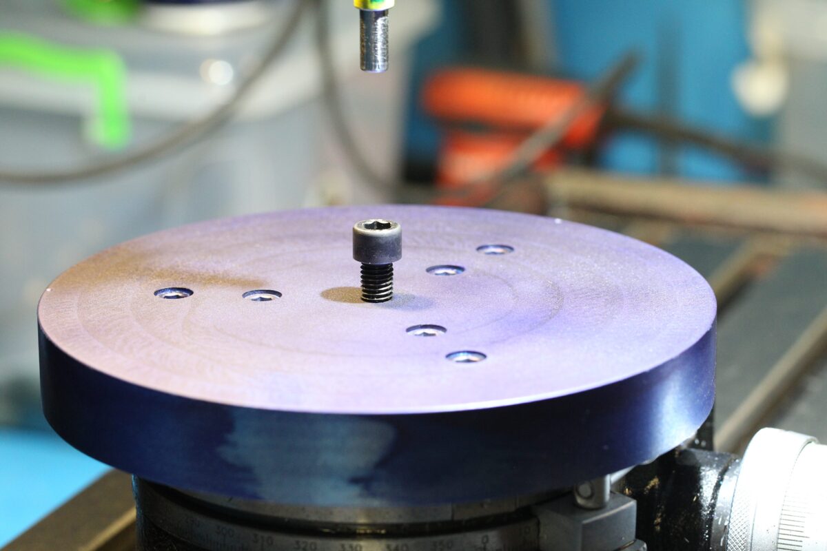
                                                      2-Milled top of disc with shoulder mill flat and revoded protruding MT2 part, all flat now. Make quick centering tool. If I fit the table to the mill table I will centre it without the disc fitted, using the then protruding MT2 part with coaxial indicator.

                                                      3-I am now ready to mark out the holes(8mm) for clamping I deed to mark out, drill and tap.
                                                      -I thinking of providing extra holes for a sine-vice strong enough(Modded) to clamp parts to fit on top of disc, it may work out.

                                                      See photos:


                                                    Viewing 25 posts - 26 through 50 (of 50 total)
                                                    • Please log in to reply to this topic. Registering is free and easy using the links on the menu at the top of this page.

                                                    Advert

                                                    Latest Replies

                                                    Home Forums Beginners questions Topics

                                                    Viewing 25 topics - 1 through 25 (of 25 total)
                                                    Viewing 25 topics - 1 through 25 (of 25 total)

                                                    View full reply list.

                                                    Advert