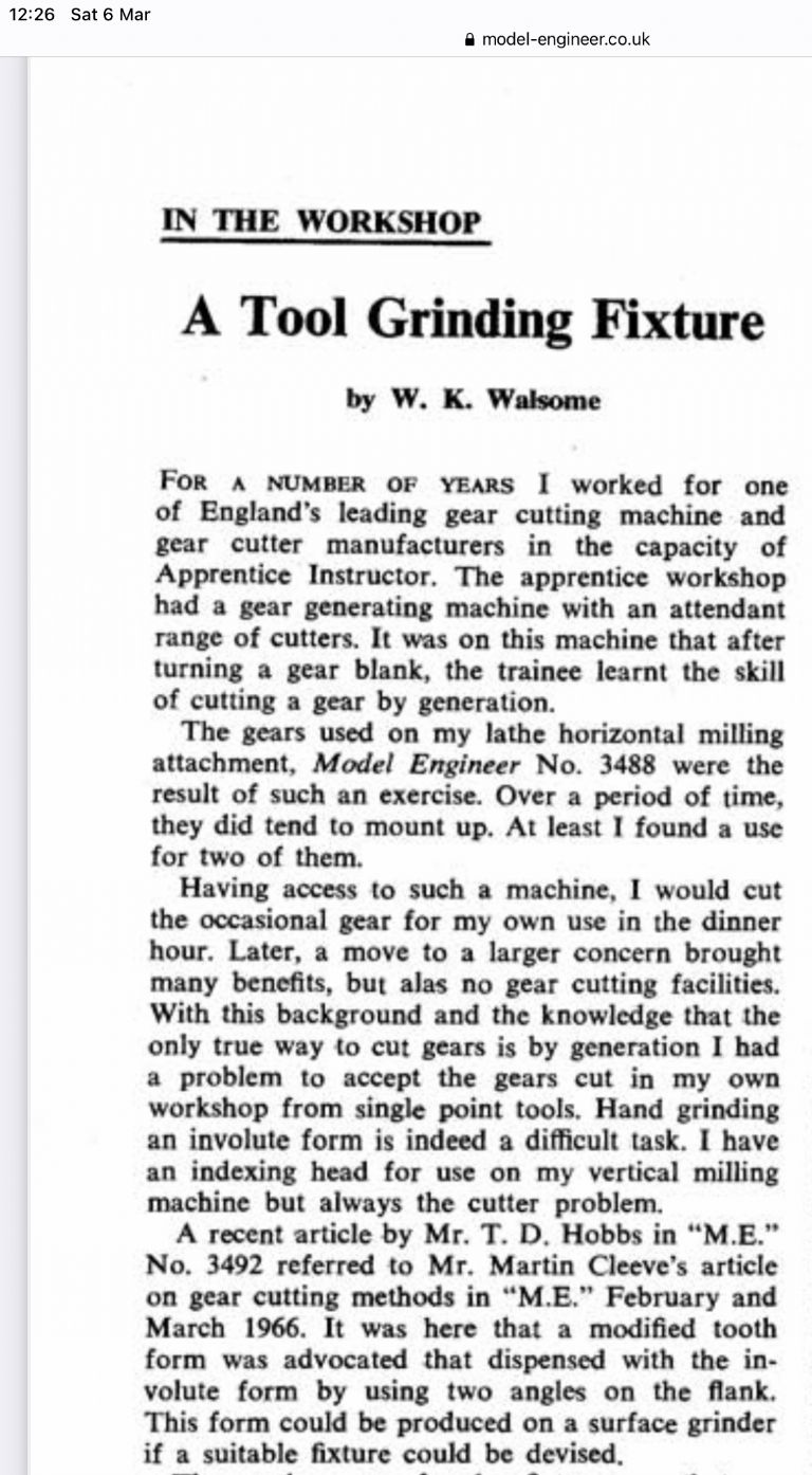
The linked article is the design for the cutter-holder, for its grinding.
We really need know what Mr. Hobbs and Mr. Cleeves (weren't they polite in those days?) described, but I wonder if it is based on the industrial process of gear-shaping?
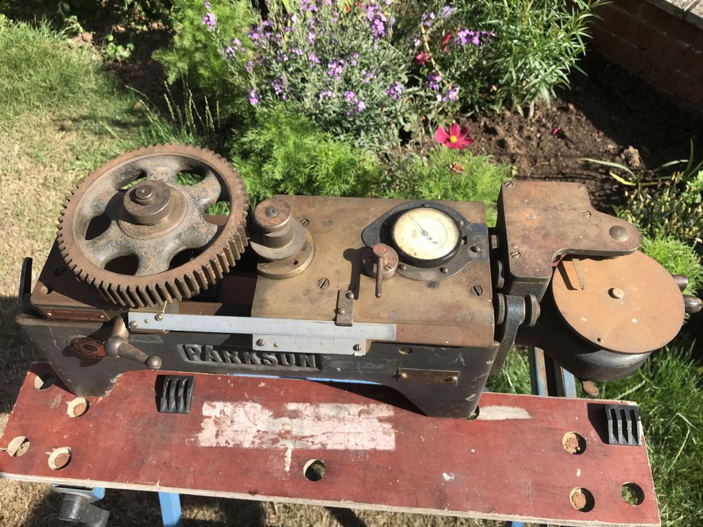
Here, the cutter is of involute-rack form, so with straight-sided teeth, reciprocated across the blank at the same time as the blank is rotated and traversed with respect to the rack, under the control of appropriate gearing. After each pass, the blank is indexed to cut the next space – the adjoining cutter teeth trimming the previous and starting the next.
This generates involute teeth of the same DP and pressure-angle as the rack; approximated mainly by the traverse / rotation increments; and I think the finished wheels are sometimes lapped together. Its advantage is of not limiting teeth-numbers by cutter.
In another version, the shaper-cutter is a formed as a gear with the appropriate clearances; and it and the blank (on its dividing-plate) are rotated with each other by suitable change-wheels. I don't know if each of such cutters can generate only a set range of teeth numbers.
It can be done on a shaper with a single-tooth, straight-sided cutter, but very much more slowly; and potentially less accurately. However, I gather a few model-engineers have obtained good results by it. It might be feasible to make a sort of insert-tooth rack in which the individual teeth are gauge-plate bars set side-by-side in a holder.
'
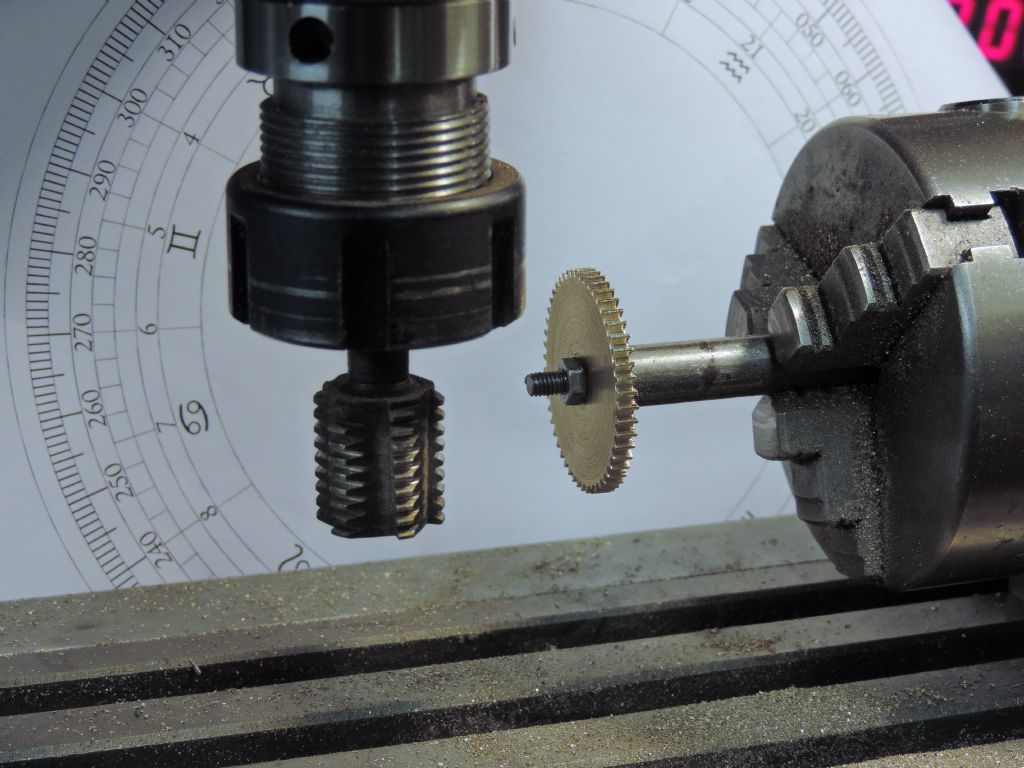
It look as if Messrs. Hobbs, Cleeve and Walsome used the same basic principle but with a revolving single-acting cutter, and it would indeed be interesting to see if their technique is worth re-visiting, though the set-up is half-way to being a gear-hobbing machine.
Mr. Walsome suggests a surface-grinder for forming the cutter, but one could equally use a tool-&-cutter grinder.
'
Or one could do as many engineering companies do nowadays.. buy standard "blank" gears and machine the bores and faces to suit. One might not gain Gold Medal though…
 Bazyle.


