Inserting An Angled Feature (Alibre Atom)

Inserting An Angled Feature (Alibre Atom)

Home Forums CAD – Technical drawing & design Inserting An Angled Feature (Alibre Atom)

Viewing 25 posts - 1 through 25 (of 32 total)
  • Author
    Posts
  • #863360
    Nigel Graham 2
    Participant
      @nigelgraham2

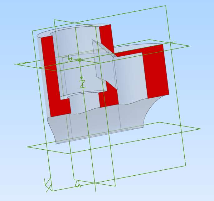
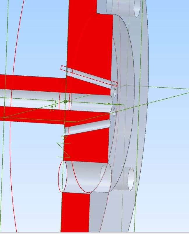
      The screen-shot is of a sectioned, non-return valve body, part of a tiny but complex assembly whose original design was more prettyness than practicality! I’m investigating an alternative way for more feasible making; but as the real thing needs extremely high-precision machining and fabricating to work at all, more as an Alibre exercise than reality.

      The arcuate horizontal section is a joint-face with a horizontal, hollow cylinder to which the component is soldered.  I I modelled the cylinder but found its internal parts too difficult to model, and the original drawings (reduced for printing in a book) are almost illegible, so I omitted them.


      The problem lies with that port sloping down into the left-hand cavity.


      My modification replaces an awkward slot with a circular hole placed to drill without damaging the upper rim of the chamber, or so low it prevents the valve working.  Such problems are normally solved by drilling horizontally through both walls, then plugging the outer wall.

      It took over an hour to plot this wretched port, and then only by cutting in from a rectangle.


      If however, I had to illustrate it as a round hole, with its axis sloping down the cut plane, and at a definite height in the cavity, how is that done, please?

      Injector Valve Ch (2)

      (Yes, the port does graze that external corner but I cannot modify the drawn outline to suit.)

      #863377
      JasonB
      Moderator
        @jasonb

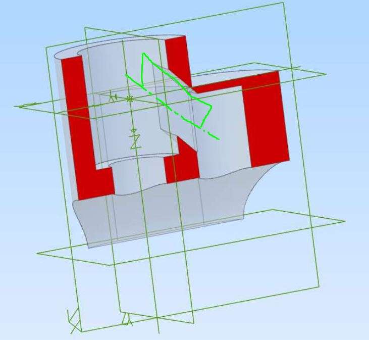
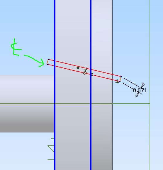
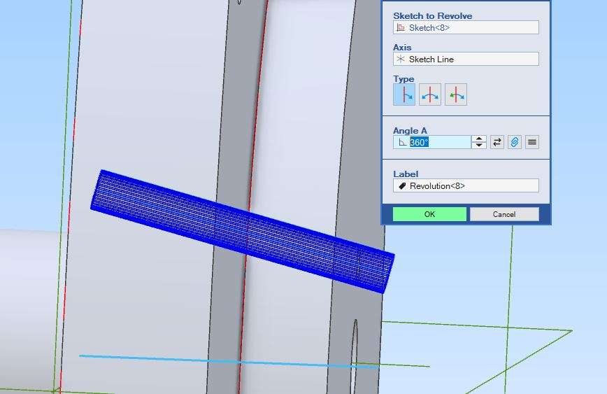
        The way to do it is to sketch “half the hole” as indicated below with one side running along the ctr line where you want to place the hole

        sketch

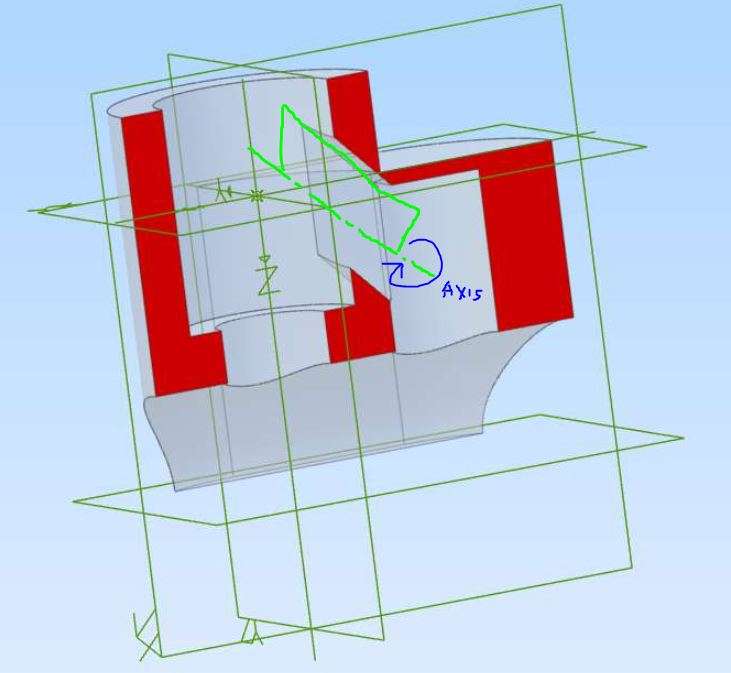
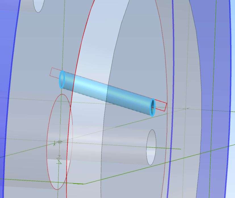
        You can then use the “cut rotate” by selecting the sketch as the item to rotate and the edge that is on the ctr line as the axis of rotation.

        axis

        Here is an example on one of my parts

        sketch 2

        axis 2

        axis 3

        axis 4

        #863378
        David Jupp
        Participant
          @davidjupp51506

          Another option is to add an angled reference plane, then use that either as the starting plane for a ‘hole’ feature, or to sketch a circle which you then extrude cut.

          There are almost always more than one single viable approach.

          #863485
          Nigel Graham 2
          Participant
            @nigelgraham2

            Jason –

            I’ve been trying your method and I can’t make it work. It won’t let me select the edge of the polygon and wants an axis instead; but the Axis tool won’t let me place one there either.

            Even extending the polygon into fresh air above the top surface didn’t allow me to select it.

            The hole is a passage inside a block so I tried sectioning it, but that didn’t help.

            I notice the corresponding tool in your screen-shots is very different to mine. I think you use one of Aibre’s professional editions and it might have features omitted from Atom.


            David –

            I had an idea it relies on adding a reference-plane. I created a very messy collection of green lines, none of them any use!

            Eventually I managed to insert a reference-plane at the appropriate angle, but that’s as far as I could go.

            Every move spins the object round and wipes out the reference-lines, so it takes me several tries to turn the thing back to where I want it.

            The Parts I draw never have a “home” position, selecting the plane I want twirls it round to face the other way and moving from sketch to model and back deletes all my carefully-made construction-lines.

            At other times, switching between views shrinks the image to a splodge you have to wind back up while chasing it around the screen. Occasionally it does the opposite, enlarging itself to a ridiculous size.

            At one point the whole gubbins locked up and I had to switch from sketch to 3D and back a couple of times to free it.

            Then I found I could not see the reference-plane and intended axis anyway.


            I gave up.

            It’s far easier to use CAD for the basic shapes and features all at right-angles to each other, and manually draw obscure details like sloping internal passages on the printed drawing.

            After all, I’m not going to publish the drawings or issue them to a machine-shop.

            #863497
            JasonB
            Moderator
              @jasonb

              The box may be asking for an axis  but you can click any one of the lines that make up the polygon.

              I have the “new look” V29 but have been doing the same with older versions which would have had the same screen a syours. David has shown this method to you before and so have I so if he did it then Atom should be able to.

              The good thing with CAD is you can easily see of the angle of your hole will miss the top edge of the part and you can deduce the angle you need to drill at, maximum diameter, etc from the CAD. That part I used to illustrate the method needed the holes position and diameter altering several times a ssubsequent part swere added an the design altered to suit those. I was just working from a few engraving sfrom 1895 so no dimensions to guide me.

              #863505
              JasonB
              Moderator
                @jasonb

                This shows it being done, I have used an older Version 27 which although Pro will have the same look to the dialogue boxes as your Atom.

                To make it easier to see where the drilled passage is going I would suggest either making the part less opaque so you can see into it.  This will also make it easier to see the sketch and click the side you want as the axis of rotation.Or as you have worked out how to do section views that can also be used to make things easier.

                You can also see me clicking the section view on and off which was your other query. I also edit the drilled hole a couple of times.

                #863506
                David Jupp
                Participant
                  @davidjupp51506

                  Nigel,

                  If a plane is selected ‘the wrong way round’ – the ‘reset view‘ tool will ‘flip’ it for you.  Planes have a ‘direction’ that you can’t do much to influence.

                  Switching to and from sketch does not delete your reference lines – you are probably opening a new sketch instead of editing the one you placed the lines in.  It may help you to rename sketches as you go, to make it obvious which one has what purpose in the design.

                  View size – there are controls to help.  You can zoom (using scroll wheel on mouse), or ‘zoom to fit’ using the Home key on keyboard.  If the view remains ‘ a tiny splodge’ then you probably have some stray figure in one of your sketches that has influenced the part extents

                  As I have said on numerous occasions – if you hit a problem, send the file to me with a clear description of the issue.  I can either point out the issue, or run a screenshare to show you.

                  #863627
                  Nigel Graham 2
                  Participant
                    @nigelgraham2

                    Thankyou both.

                    I think a lot of the difficulties I have stem from how I learn things, and this is not only CAD; nor restricted to anything “academic” which includes difficult software.

                    I progress only so far then at best stay there at that level, but often with gaps on the way I can never fill, or obstructions I can’t overcome. Sometimes the obstructions are tiny but enough to stop that route.

                    So in CAD, such an obstruction comes by not grasping how to plot some particular feature, even if I could make the real object. If it were my design I’d need either complete the drawing manually or re-design the component. Not just in that project but any later with similar features, because my brain would always remember that type of feature as a stop-block.

                    That’s neural physiology for you!

                    I was too ambitious with that odd-shaped valve body- but the original design was even worse.


                    David –

                    The switch between sketch and model I meant, and use, is the big one at the left-hand end, labelled “Activate” or “Deactivate” sketch.


                    Jason –

                    Using one side of the generating polygon is exactly what I was trying to do, but nothing happened. I tried it on both a section view and a translucent complete view, but that made no difference.

                    In the original design the larger part of the body is just a cylinder. It is the overflow valve for an injector designed by D.A.G. Brown, and his over-reduced drawings are on p.38 of his book on making them.

                    The outlet is a tiny horizontal slot, not a sloping hole. Joining it to the hole down through the main body is a tiny, extremely delicate, ‘C’ section, inverted trough, sloping down at 45º. I know I could never make and fit that reliably. That’s what I was trying to replace.


                    I picked it largely as Alibre Atom revision because I’ve not used it for some months, but also vaguely wondered if I could make one. No. I cannot machine anything to the necessary limits.

                    (One modification Brown suggests elsewhere in the book is facing the inside of the steam cone flange back by 0.005″. Errrr…. How would you hold very accurately by less than half its length a tiny thing that would rattle inside a broad bean?)


                    I combined the pure CAD exercise with investigating a potentially easier and more reliable, though less pretty, design. And that’s where I hit the buffers.

                    I’ve probably reached my own limit of ability with Alibre Atom, with this injector.

                    #863631
                    David Jupp
                    Participant
                      @davidjupp51506

                      Nigel,

                      If you use Activate 2D sketch it will generally start a NEW sketch (there are exceptions).  It does not delete what you have already sketched.

                      To edit an existing sketch either

                      • select the sketch in the Design Explorer and then click Activate 2D sketch button (you’ll be prompted whether to edit the selected sketch or to start a new one).  OR
                      • Right click the sketch in the Design Explorer and choose Edit from the context menu.

                      If the re-orientation of the workspace on starting a sketch is troubling you – that can be turned off (though it is usually helpful behaviour).

                      System Options -> Parts/Assemblies -> Sketching :  un-check ‘Snap to working plane’

                      #863751
                      Nigel Graham 2
                      Participant
                        @nigelgraham2

                        Screenshot 2026-09-05 221755

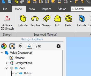
                        This is the control I’ve always been using, below the word “File”, but without selecting any specific sketch from the list below it first. So is that where I’d been going wrong?

                        I have just experimented and found the Edit tool only works with Model selected.

                        #863777
                        David Jupp
                        Participant
                          @davidjupp51506

                          Nigel – right mouse button click (unless you have mouse set for left handed operation) on any feature or sketch in the Design Explorer will re-open it for editing.

                          It also ‘winds time back’ to the state the model was in when that feature or sketch was added.  After finishing the edit, you have to Apply/OK (for feature) or Exit (for sketch), and then Generate to Last Feature (F5) to update the model and get any later features to display.

                          #863899
                          Nigel Graham 2
                          Participant
                            @nigelgraham2

                            Thankyou David.


                            I think I should save these instructions somehow. Left on the Forum, they vanish into the depths.


                            I didn’t know there is that quick ‘Generate’ way. I thought that’s what dragging the “bone” shape highlighter down the index is for.

                            So I found I can edit the polygon I’d wanted to revolve to generate a hole; but still cannot understand how Jason managed to make that method work. The Revolve Cut tool won’t let me select its edge, nor can I plot an axis (which the tool prefers anyway) along that edge. It’s even harder because the editing and axis tools are not on the same page; and the model page seems to lock the polygon so it shows but can’t be selected.

                            My attempts still sent it haywire: shrinking it to a tiny blob any old way up, any old where on the screen, laborious to recover.

                            Nor was I able to generate the passage from an auxiliary plane, though it’s not helped by the object’s awkward shape. (As a design exercise rather than only CAD practice I have worked out an alternative I can both draw and if I want, perhaps make, but have not tried drawing it.)


                            Should never have dismantled my drawing-board….

                            I’m stuck on this one silly exercise I chose to do, thinking it might not be too difficult; but it has proven impossible for me.

                            #863917
                            David Jupp
                            Participant
                              @davidjupp51506

                              ‘Generate to last feature’ does the same as dragging the dog bone to the bottom of the Design Explorer.

                              Do you by any chance have ‘snap to grid’ enabled?  It can make selecting difficult to impossible in some cases for figures that don’t lay directly on the grid.  I prefer to disable snap to grid.

                              Selecting the edge of a polygon as revolution axis should be as simple as hover cursor over it and click.

                              Check ‘snapping threshold’ setting – if it is zero, you have to be ridiculously precise with the mouse to select things, too large a value can also make selection difficult.  Optimum value does depend upon the size of part you are designing – I find 3.0mm works well for me.  System options -> Parts/Assemblies -> Sketching :  Snapping Threshold.


                              #863924
                              JasonB
                              Moderator
                                @jasonb

                                I also find zooming in can help when selecting small features

                                #863950
                                Nigel Graham 2
                                Participant
                                  @nigelgraham2

                                  Thankyou.


                                  David –

                                  I think I had the Snap to Grid off. There’s no certainly no grid displayed.

                                  I use the little view symbols to show a surface full-on, but I was never able to work out quite which way round that valve body was. I often find it hard to choose the appropriate base plane for what will be a Part of an Assembly, and that might be why that particular model was so awkward.

                                  I think I usually use a Snap threshold bigger than 3mm, but it’s not too large and isn’t usually a problem.

                                  The polygon I was trying to select was a reasonable size for visibility and not tangled up in other constructions, but whatever I did would not work.


                                  Jason –

                                  And following from above, I do zoom into the view when trying to pick some fine detail out of the clutter.

                                  I watched your video carefully and could not work out what I was doing that was any different from your method, although the revolve tool only asked for an axis. I’ve used Revolve -Extrude and -Cut without difficulty in the past, but this one just did not work. I noticed yours displayed “Edge” to select but mine only shows “Axis”.

                                  I have deleted those useless injector drawings, all 5 Parts, but tried a quick test. I modelled a rectangular block, created a thin rectangle in it, sloping down through it at no particular point or angle, and tried turning that into a hole.

                                  Same result. Despite the rectangle protruding from both surfaces, it was not possible to select the edge for the revolve-cut. Nor could I plot an axis along it; but selecting the axis tool hides the rectangle. Even if I could, I can’t see how to make it link two points at defined locations.

                                  I threw that away and tried again, thinking the problem was having used the plane that was the shape’s base. This time I ensured all three base planes pass through the block. Still no good. Revolve Cut needs an axis only. So I tried giving it an axis – that failed too.

                                  It’s as if I’m asking the software to use something it does not offer. Essentially,  I cannot plot a feature inclined through some part, rather than perpendicular to a single surface.

                                  #863967
                                  David Jupp
                                  Participant
                                    @davidjupp51506

                                    Nigel,

                                    Jason’s example only showed ‘axis’ for the revolve cut tool – it did not show edge (though you can use a sketch line as an axis).  I don’t know where you see ‘edge’.

                                    You should be able to select a straight line from a sketch to use as an axis of revolution – as long as the sketch itself is visible, and not buried inside the solid.  This is where using precise section view, or making sure the sketched rectangle extends well beyond the bounds of the solid can be useful.

                                    Make sure that the Axis field is active (has a slight blue hue) – click in that field to make it active.  You can only select the axis when that field is active.  Depending upon the exact order of operations, the axis field may not be active – say if you’ve just set the sketch to use in the sketch field of the dialogue.

                                    #863972
                                    JasonB
                                    Moderator
                                      @jasonb

                                      You don’t need an actual axis line to us ethe revolve tools both solid or cut. You can use part of a sketch or even click another feature created earlier in the design.

                                      Make sure you click the revolve cut tool before trying to select the edge/axis, if you are trying to select it first it won’t select

                                      Once again you have deleted the files so there is little hope for David or myself to look at them and see what might be giving you problems. We can’t really help you if you don’t help yourself. Though if you can pull them out of your recycle bin there may be hope.

                                      #864008
                                      Nick Hughes
                                      Participant
                                        @nickhughes97026

                                        Just to chip in and back up Nigels experience.

                                        I also can not select the edge of a simple rectangle, sketched on (in my case) the XY plane, for the revolve axis.

                                        Opening the Revolve tool, causes the sketch to disappear from view and can only be shown again by clicking on it in the Design Explorer.

                                        I can attach an Axis to the edge and use this for the revolve, but this should not be required.

                                        Using Deign Expert, V29, Build 29069.

                                        #864011
                                        David Jupp
                                        Participant
                                          @davidjupp51506

                                          Nick,

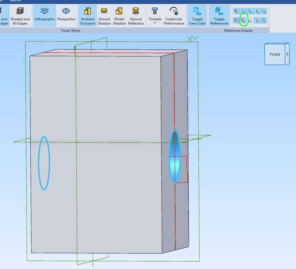
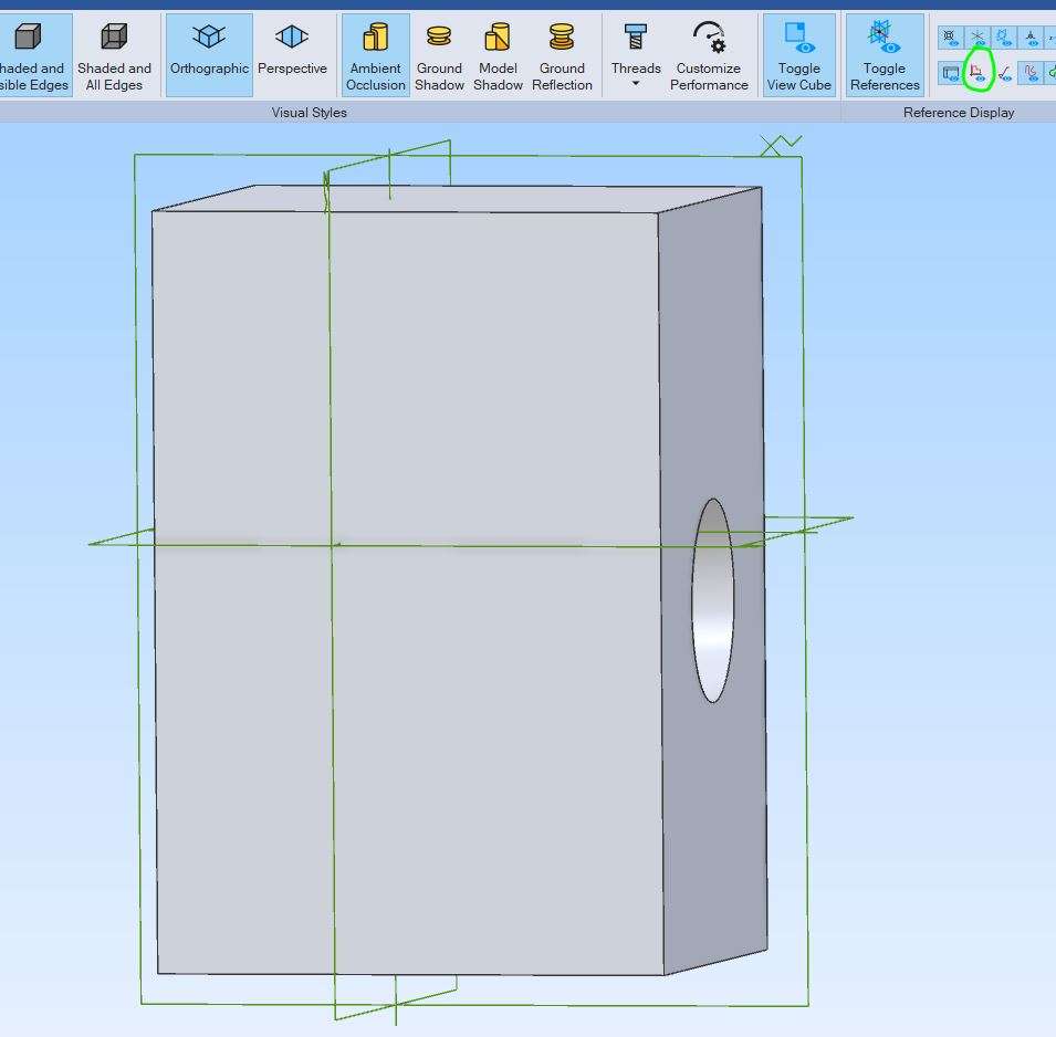
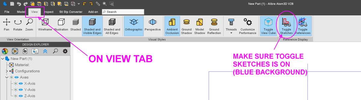
                                          Do you have sketch visibility toggled on in the View tab of the ribbon?


                                          #864013
                                          Nigel Graham 2
                                          Participant
                                            @nigelgraham2

                                            I was getting (more) confused.

                                            Yes: “Edge” is in the Axis tool, not Revolve, but even there the instruction symbols implies it has to be an edge between two surfaces of a solid, not the side of a flat polygon.

                                            Your first example, using the holes through a flywheel, has the “Axis” line in a form labelled “Sketch to revolve”, showing the Axis 3-line symbol and the phrase “Sketch line”.

                                            So your form differs from my version’s.


                                            As I said, I tried this morning with a far simpler example, just a rectangular block with a rectangle protruding into thin air to make it easier to select. That would not work either.

                                            Just tried yet again. This is what the tool shows:

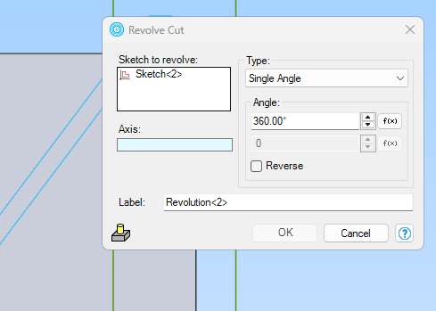
                                            Screenshot 2026-09-07 173431

                                            The rectangle does stick out of the block, top and bottom, but cannot be selected for revolving. No way to select it. Revolve Cut wants an axis I cannot provide either.

                                            I drew a little rectangle lying along the X-axis. That will revolve to make a cylinder, but only around the X-axis. Nothing else.

                                            There must be very tight limits on what these tools can do, but I cannot work out what they are.


                                            I finished late last night deciding this aspect of Alibre Atom is too advanced. That’s when I threw those files away.

                                            Random problems like these are why I use CAD far less than I’d originally wanted. I can plot only very simple shapes all perpendicular to each other, so never use it for designing machines with lots of odd-shaped bits.


                                            I am very grateful for your advice but I cannot grasp this revolve-cut technique and likely never will.

                                            #864018
                                            JasonB
                                            Moderator
                                              @jasonb

                                              Nick and I think Nigel too, before your sketch disappeears is it blue?

                                              As David says if you do not have sketches marked as vissible you wil not see an edge to click. It’s a feature I always have visible and expect David does too.

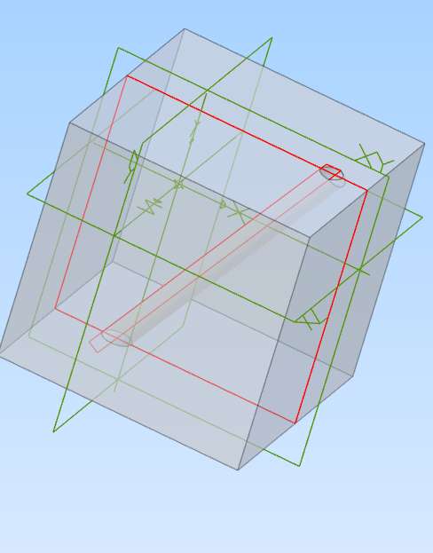
                                              This is with it visible an dyou can see the sketch in red along with the previous one used to sketch the box

                                              view sketch

                                              If I unclick the sketch visibility then that blue sketch (most recent item) will disappear if you click the revole (and other) tool. So you will not be able to click on a side or end of the sketch


                                              view sketch 2

                                              #864019
                                              JasonB
                                              Moderator
                                                @jasonb

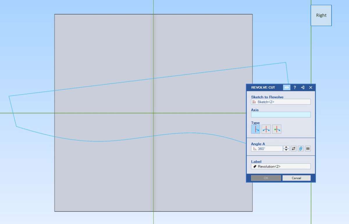
                                                This replicates Nigel’s screen image. The sketch is in blue and the box has the sketch No in the “Sketch to revolve” box but you can’t click the blue sketch. Making sketches visible will turn that sketch red as the cursor hovers over a line that could be an axis and then you can easily click a part of it.

                                                blue

                                                #864020
                                                JasonB
                                                Moderator
                                                  @jasonb

                                                  Here I try to select part of the sketch but can’t. Turn on visibility and then as soon as the cursor is over a line it turns red and can be clicked

                                                  #864028
                                                  David Jupp
                                                  Participant
                                                    @davidjupp51506

                                                    Nigel,

                                                    “Sketch Line” in the axis box indicates that Jason had selected a line in a sketch to act as the axis of revolution.  Form in my version is not substantially different from yours – I even set my system to run in Atom3D mode as a double check that I’m not misleading you with Pro/Expert options that you don’t have.

                                                    I could probably sort this out in a very short space of time with a screen share.

                                                    Toggel Sketches (Atom3D)

                                                    #864047
                                                    Nigel Graham 2
                                                    Participant
                                                      @nigelgraham2

                                                      Thankyou!

                                                      At Last!

                                                      It’s not the most obvious move.

                                                      Screenshot 2026-09-07 230334

                                                    Viewing 25 posts - 1 through 25 (of 32 total)
                                                    • Please log in to reply to this topic. Registering is free and easy using the links on the menu at the top of this page.

                                                    Latest Replies

                                                    Viewing 25 topics - 1 through 25 (of 25 total)
                                                    Viewing 25 topics - 1 through 25 (of 25 total)

                                                    View full reply list.