
Richard Simmonds’ “How To Make A Weight Driven Clock”

Richard Simmonds’ “How To Make A Weight Driven Clock”

Home › Forums › Clocks and Scientific Instruments › Richard Simmonds’ “How To Make A Weight Driven Clock”

Viewing 7 posts - 1 through 7 (of 7 total)
  • Author
    Posts
  • #872485
    iacooper
    Participant
      @iacooper

      Technically this isn’t my first post to the forum, but effectively it is.  I’ve lurked as a reader for a number of years with nothing of value or interest to offer to the forum, however after 12 months of work I have recently completed my first clock project, following the plans of Richard Simmonds’ book “How To Make A Weight Driven Clock” which was first published in spring of last year (2025).

      Although I’m not attempting to document the process (after all, that’s the purpose of the book), I have ended up with numerous photos snapped along the way before finally arriving at the finished working timepiece, which I’m happy to share across a series of posts if members are interested.

      Having reached out to the author I have found him most friendly and supportive, he was upset to learn of some of the dimension issues I encountered along the way and has collated my feedback to provide to the publishers should there be a reprint.  In the mean time if anyone else is contemplating the project I suggest they contact Mr. Simmonds so he can share the additional notes, clarifications and corrections.

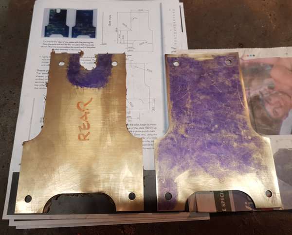
      Anyway, we’ll start off with the main plates:

      1

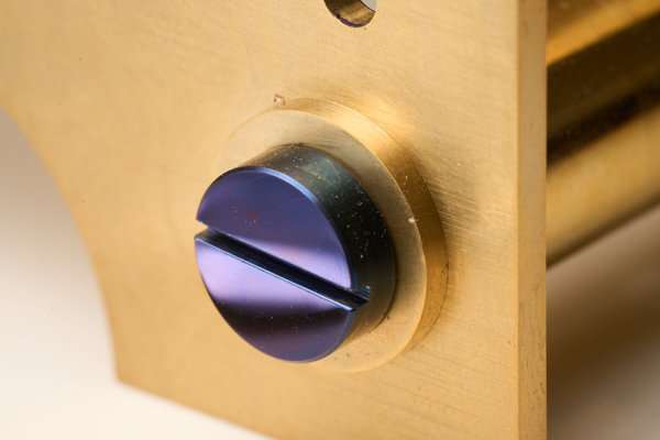
      Followed by spacer pillars, washers and custom screws to hold it all together…
      2

      3

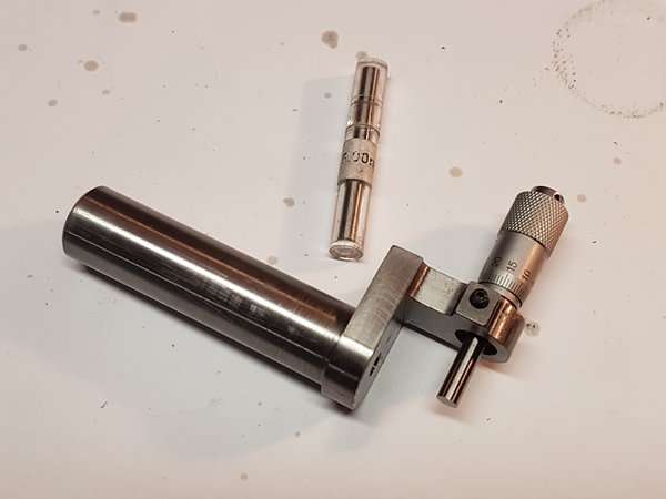
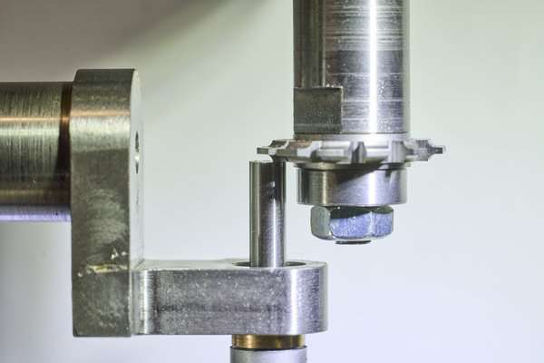
      The material for the wheels was cut out, at which point I took a detour to make myself a tool for accurately setting the gear cutter on centre height.

      Through the centre is a close reamed 5mm hole into which a 5mm gauge pin can be inserted.  The micrometer dial can then be set to 2.50mm and positioned against the side of the pin before nipping the grub screw to hold it in place.  With the pin removed this means with the micrometer dial set at 0.00mm it is on the centre line of the tool’s shank.

      6

      …you can now set the micrometer to half the width of the cutter, then adjust the cutter so it just meets the end of the micrometer:
      7

      The cutter is now on centre height  (or at least should be if everything was made correctly)

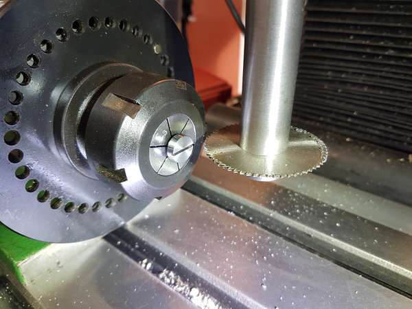
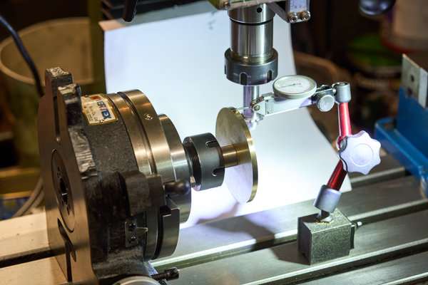
      I could now ensure the wheel blank is truly set up concentric and true…

      8

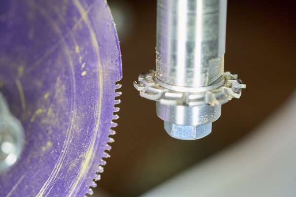
      Before setting forth on the adventure of cutting my first gear wheels
      9
      (Ok, technically I had another side-project of having to make a dividing plate to get the right ratios for one of the clock wheels – but hey ho, simple work with the miling machine DRO)

      With that I’ll leave things be and pick up with a few more photos on another evening…

      Ian.

      #872518
      Nigel Graham 2
      Participant
        @nigelgraham2

        Excellent!

        Thankyou for this contribution and we look forwards to the continuation.

        #872559
        Michael Gilligan
        Participant
          @michaelgilligan61133

          A very useful setting-tool there, Ian … Thanks for sharing the photos

          MichaelG.

          #872569
          renardiere7
          Participant
            @renardiere7

            Yes please! Do carry on with more photos. I very much like your setting tool and could see how it might have other uses eg in tool and cutter grinding and possibly in setting up rotary table offsets.

            #872616
            Martin Johnson 1
            Participant
              @martinjohnson1
              On renardiere7 Said:

              Yes please! Do carry on with more photos. I very much like your setting tool and could see how it might have other uses eg in tool and cutter grinding and possibly in setting up rotary table offsets.

              Another vote for more photos & tales from your workshop.

              Renardiere reminded me that Prof Chaddock described a similar setting tool for ball end cutters on the Quorn.

              Martin

              #872620
              Andrew Crow
              Participant
                @andrewcrow91475

                I’ll add another vote for more detail and photo’s, always good to see top quality work.

                Andy.

                #872714
                iacooper
                Participant
                  @iacooper

                  Thank you for the support.

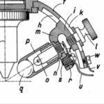
                  I can claim no credit for the centring micrometer as this is something mentioned in Malcom Wild’s book, “Wheel & Pinion Cutting in Horology”.  Although it shows a couple of photos of the tool in use and a description, it goes on to comment that such a tool “...can be readily purchased“.  Alas, the book seems rather light on the detail of exactly where such a tool can be readily purchased!  No matter, a bit of time with crayons sketched out something possible.  Three lumps of steel were silver soldered together and then machined all over.


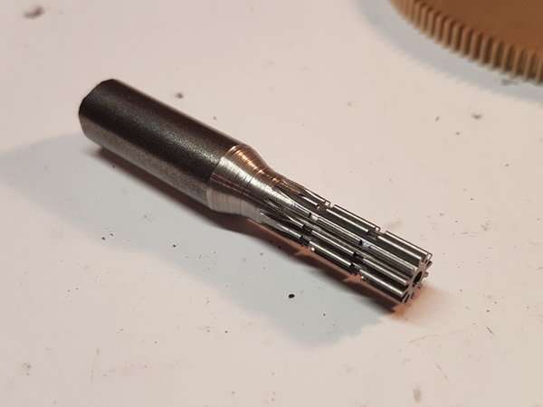
                  With all the wheels sporting teeth I could move on to the pinions, feeling slightly cautious following numerous comments found online about how much extra care is needed compared to machining brass wheels.

                  I don’t have flood coolant, but numerous comments suggested this would be important for the pinion cutting.  I invested in a cheap windscreen washy pump kit from Amazon (or was it EBay?) which was hooked up to a variable bench power supply so I could adjust the voltage/flow.

                  When it came to coolant choice itself I went with white spirit – might not be the best option, but it would certainly be better than nothing at all, was cheap, and readily available.

                  A small plastic tub was located under the cutting operation to catch the overspill.  When that filled up I just paused machining, tipped the used coolant through a kitchen-paper filter in the top of a funnel to remove the metal shavings as it went back into the pump reservoir and then started again.

                  Whilst the brass wheel teeth were cut through at full depth, the pinions were tickled into being with multiple rotations at lighter depths, with the cutter running rather slower and my manual feed rate taking it steady as well.

                  I was unsure about providing tailstock support, but decided to wing it and try without…

                  11


                  The book talks about leaving the pinions unhardened, but I decided to pack them with boric acid to prevent scale and then hardened and tempered them before finally polishing to a mirror finish.


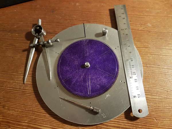
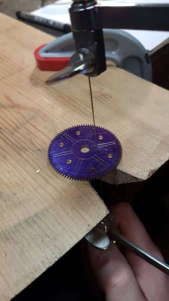
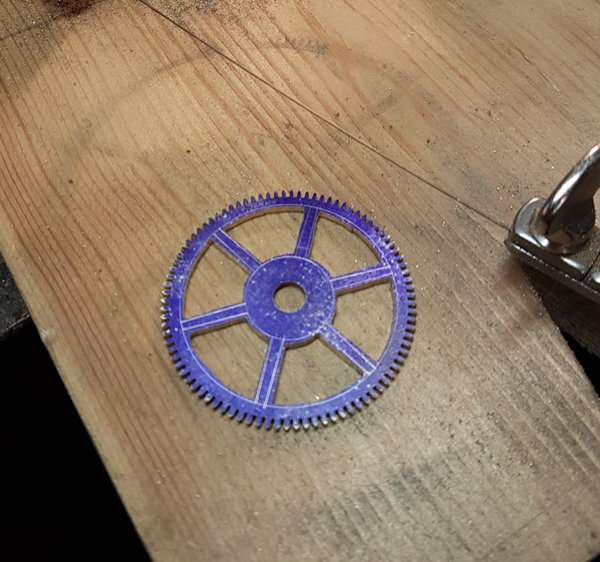
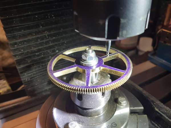
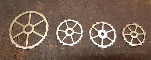
                  With the gear cutting all complete, the next focus was crossing out the wheels to reveal the spokes.
                  Some effort with 2D CAD worked out the diameter and radius where I needed to locate pegs (heavily disguised as drill bits) on a jig against which I could rest a straight edge to produce the spoke lines for all the various diameters of wheels:

                  10

                  13 14

                  I didn’t like my chances of accurately filing to the line, especially as keeping the whole thing balanced seems an important idea, so I went to the rotary table:

                  15

                  I’ll admit the process was not quick and my heart was in my mouth much of the time – especially with smaller diameter wheels which used decidedly smaller end mills.  Despite this I emerged from the process with the same number of cutters I started with.

                  Towards the end of the build I came to make the weight pulley, by which point I didn’t have the enthusiasm to set up with the rotary table again, so for that I filed out the spokes and rim by hand despite the material being somewhat thicker. The end result seems just as good and wasn’t really any longer time wise.  In either case, all the final finishing with fine polishing papers was careful manual work anyway.

                  16

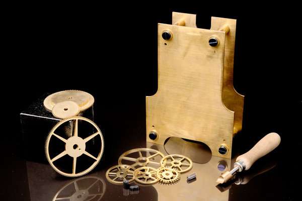
                  So here we are with all the components made to date (including a bronze screwdriver designed to fit the large blued screws so I don’t risk damaging them as they get handled)

                  17


                  Ian.

                Viewing 7 posts - 1 through 7 (of 7 total)
                • Please log in to reply to this topic. Registering is free and easy using the links on the menu at the top of this page.

                Latest Replies

                Viewing 25 topics - 1 through 25 (of 25 total)
                Viewing 25 topics - 1 through 25 (of 25 total)

                View full reply list.