How Did Lawrence Sparey Make It Work?

How Did Lawrence Sparey Make It Work?

Home Forums General Questions How Did Lawrence Sparey Make It Work?

Viewing 25 posts - 26 through 50 (of 68 total)
  • Author
    Posts
  • #326969
    Clive Foster
    Participant
      @clivefoster55965

      Bazyle

      Your way is much more sensible for the Home Shop Worker.

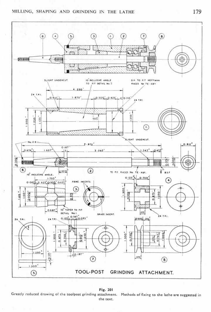
      Unfortunately Sparey's drawings seem to be straight out of the Jones & Shipman drawing office "Small Very High Speed Grinding Spindle". Two deep groove ball bearings at the pulley end to properly support it against long flat belt flap and similar effects despite the relatively large internal clearances needed when running really fast. The grinding wheel end is supported by a taper adjustable plain bearing 1 3/4 inches long with two active bearing surfaces 5/8" long. Similar designs found in old style bench precision lathes and the like. Highly polished glass hard bearing surfaces on both shaft and bearing. If properly set to the appropriate negligible clearances and supplied with the right oil such bearings will run very fast for a very long time working at effectively zero clearance. On a proper grinder asking for sub tenths cuts will get you sub tenths cuts if such bearings re used

      Sparey calls for matching 10° tapers on both bearing and housing. The housing taper is 1 3/4 inches long starting almost an inch in from the end. That inch being needed to fit the end cap part no 4. Creating those matching tapers is going to be very challenging on any typical Home Shop lathe, especially a Drummond or similar pre war breed. Even with the 1024's superb taper turning attachment not a walk in the park. Doing it by offsetting the topside looks to be a nightmare. Especially given that a high finish is needed and that the angles are close to those of self locking tapers. Jam up potential on test fit is very high! Glass hard running surfaces are mandatory on such bearings if clearances are to be appropriately close. If you can't arrange that there is no point in going to such trouble as a carefully made plain bearing will be as good.

      Having arranged the two tapers you still have to get the pulley end bearing bores dead concentric with the assembled taper bearing and shaft. No spiffy tenth thou indicators in the Home Shop then.

      Realistically, as drawn, I reckon it would have to be a "foreigner", "homer" or "government" job for a decent toolroom machinist able to pull in favours from other parts of the factory.

      Clive.


      Edited By Clive Foster on 13/11/2017 14:20:10

      #326971
      Clive Foster
      Participant
        @clivefoster55965

        Neil

        You posted whilst I was typing. Normal practice with this sort of spindle would be to simply clamp the two end bearings against the spindle shoulder via the extension on the pulley. Cap 7 just keeps the assembly in the body.

        The ball bearings are only to support the pulley and stop things floating sideways. Its the big taper adjustable plain bearing that does all the real work. In that era small, off the shelf, single unit ball bearings intended to run at the speed envisaged would have too much clearance to properly support an accurate grinding spindle. Serious marks on the work if not outright errors will result of such bearings are used. Magneto types can be set tighter and can be got away with if true precision grinding is not needed. By industrial standards they won't last long tho'.

        Clive.

        Edited By Clive Foster on 13/11/2017 14:15:18

        #326972
        David Standing 1
        Participant
          @davidstanding1
          Posted by Clive Foster on 13/11/2017 11:46:39:

          At the original 1948 printing date there is pretty much no way any ordinary Model Engineer would have a hope of making the thing to a sufficiently good standard with the sort of lathe typical of the time. A Southbend or Atlas would perhaps be up for it but Drummond, Portass, Zyto et al. Ferrgedditt. Heck would Home Shop Guy even have a micrometer then. Even by 1960 when Myford 7, Boxford et were making some penetration it wouldn't be a straightforward job.

          Piece of cake for a Super Adept devil

          #326976
          Mike Poole
          Participant
            @mikepoole82104

            I think Lawrence Sparey had a Myford ML7 in 1948 which must have been a very early one. Although certainly not a beginner project I think It would not be beyond the abilities of some ME readers to have built this spindle. I would imagine that there always have been ME readers who either own or have access to high spec machinery, perhaps more people in days gone by were toolmakers and machinists and had the skill and access to make stuff like this. With the decline in manufacturing there are not so many people who have served a practical apprenticeship but over and over again people learn the skills and produce outstanding work.

            Mike

            #326981
            Chris Trice
            Participant
              @christrice43267
              Posted by Clive Foster on 13/11/2017 11:46:39:

              At the original 1948 printing date there is pretty much no way any ordinary Model Engineer would have a hope of making the thing to a sufficiently good standard with the sort of lathe typical of the time. A Southbend or Atlas would perhaps be up for it but Drummond, Portass, Zyto et al. Ferrgedditt. Heck would Home Shop Guy even have a micrometer then. Even by 1960 when Myford 7, Boxford et were making some penetration it wouldn't be a straightforward job.

              That's what they said about the pyramids. Never underestimate the power of determination. It might take longer but not impossible.

              #326987
              Neil Wyatt
              Moderator
                @neilwyatt
                Posted by Mike Poole on 13/11/2017 16:18:07:

                I think Lawrence Sparey had a Myford ML7 in 1948 which must have been a very early one.

                I think some photos show an ML7 but others are clearly of a drummond.

                Sparey was a very skilled machinist: 'while essentially simple, accurate workmanship is essential'!

                #326997
                Mike Poole
                Participant
                  @mikepoole82104

                  My edition is 1974 and has clearly had a rewrite since 1948, it would be interesting to see a first edition to see how extensive the rewrite was and what equipment was illustrated. If the photo in my edition was taken in 1948 l think Sparey would have been about 48 which I could believe from the photo but I could also believe plus or minus 10 years aswell.

                  Mike

                  #326999
                  Mike Poole
                  Participant
                    @mikepoole82104

                    In "A Man and his Lathe" Sparey refers to his own lathe being an ML7 and a hard used one at that.

                    Mike

                    #327000
                    Robbo
                    Participant
                      @robbo

                      Neil has his pdf copy of the original article in Model Mechanic, but as this has aroused such interest I have scanned it again in jpeg format and created an album for it "Sparey Grinding Attachment".

                      This is now in my Albums for all to see.

                      #327003
                      Michael Gilligan
                      Participant
                        @michaelgilligan61133
                        Posted by Carl Wilson 4 on 13/11/2017 13:08:45:
                        All of that above may well be the case.

                        There's still no driving feature.

                        .

                        Thanks to Robbo … I think we have the answer to that

                        See the note about Detail No. 8

                        MichaelG.

                        #327005
                        Neil Wyatt
                        Moderator
                          @neilwyatt

                          Thanks Robbo,

                          The original text states "the pulley has to be nutted up very tightly as it clamps the whole ball-race assembly together. The bore should be a tight drive fit on to the end of thee shaft as no keyway and key are provided".

                          So the drawing is in error and the end cap must be bored 3/4 full right through.

                          #327008
                          Carl Wilson 4
                          Participant
                            @carlwilson4

                            Thanks for that! It’s a rum design and no mistake.

                            #327009
                            Mike Poole
                            Participant
                              @mikepoole82104

                              Perhaps Mr Sparey knew the drawing was wrong and posted that article as F Williams.

                              Mike

                              #327024
                              Bazyle
                              Participant
                                @bazyle

                                Ah, thanks for the drawing Robbo. now all become clear. The bronze bearing is a bit like a Drummond headstock so not unreasonable for its time except for the cost of a big lump of the metal.
                                The drawing makes the error in the rear cap clear and I'm sure anyone actually trying to make it would quickly realise the problem and adjust the hole and make a spacer. At least it is an easy fix unlike some errors on loco frames that have got through to print.

                                As to boring the taper and fitting the bearing. Is it any more difficult than making a Morse taper?

                                #327032
                                Clive Foster
                                Participant
                                  @clivefoster55965

                                  Posted by Bazyle on 13/11/2017 21:38:32:

                                  As to boring the taper and fitting the bearing. Is it any more difficult than making a Morse taper?

                                  Yes lots harder due to the number of things that have to be kept concentric to very close limits if its all to spin freely :- bearing bore, two tapers, ball bearing housings and a taper mandrel for mounting the housing when doing the bearing bores. Try figuring out the job task sequence needed to avoid disturbing a set-up that will be needed later. Its like one of those unhitch the wire puzzles. Probably no taper turning attachment on the lathe and certainly no spiffy indicators at home worker friendly prices then to help. Maybe a Unique at best. Whilst a Unique is a remarkably good performer given its bent bit of tin construction the tenths thou accuracy needed to pick things up again is beyond its pay grade. One thou is different matter. Don't forget that the bearing taper in the housing starts nearly an inch in which really doesn't help.

                                  Detail reading shows that this article really needed a heavy dose of the editorial blue pencil as the design is completely inappropriate to both its target audience and the actual intended use. The second paragraph confirms that its basically a copy of a proper very high speed spindle design intended for up to 30,000 rpm. The complexity and difficulty of the taper adjustable plain bearing is quite unnecessary if, as suggested in the next to last paragraph, only 3,000 or so rpm is likely in practice. At such low speeds might as well use a simple plain parallel bearing scraped or lapped to fit. Scraping that lump of phosphor bronze to properly fit the shaft as suggested is going to be nigh on impossible for any ordinary guy in any home workshop. Frankly a simple shaft in a pair of Lucas magneto bearings run tight with oil feed arrangements would do as well and be much, much easier.

                                  That extension shaft on a 2BA thread doesn't seem a very happy concept. Especially as its suggested that a larger diameter external wheel could be fitted direct on the thread! Um. No mention of the size of wheel that should be used either. Suggesting that left or right hand threads should be chosen depending on which direction the wheel will rotate grates too. A left hand thread 2 BA tap would never have been cheap.

                                  Having had my knuckles rapped a time or six in the past for letting complexity induced by reaching for irrelevant and theoretical advantages I know just how easy it is to get locked into an unsuitable, but superficially elegant design. My experience is that mistake is always compounded by silly pre-schoolboy errors!

                                  Clive

                                  #327036
                                  Carl Wilson 4
                                  Participant
                                    @carlwilson4

                                    So after all this, the answer to the question posed in the original post is – He didn’t.

                                    I don’t care though. It’s still a great book.

                                    #327047
                                    Ady1
                                    Participant
                                      @ady1

                                      In his defence, there is a note at the bottom of my 2nd edition

                                      "Greatly reduced drawing of the toolpost grinding attachrnent Methods of fixing to the lathe are suggested in the text"

                                      grinder3.jpg

                                      #327050
                                      Carl Wilson 4
                                      Participant
                                        @carlwilson4

                                        Indeed. As I say I think it’s a great book and this doesn’t detract from it for me.

                                        There are lots of nice pictures of Drummonds in it. These inspire me to take the 3 plastic crates full of bits that purport to be a Drummond B type that are currently languishing in my workshop and get on and restore the poor thing.

                                        #327053
                                        Hopper
                                        Participant
                                          @hopper

                                          Yes, it is a geat book — on lathes. I think if anyone wants to make a grinding spindle they would be better off to consult the WPS book "Spindles" for more modern designs using readily available and more user-friendly tapered roller bearings and the like.

                                          #327062
                                          Carl Wilson 4
                                          Participant
                                            @carlwilson4

                                            Agreed Hopper.

                                            #327091
                                            Neil Wyatt
                                            Moderator
                                              @neilwyatt

                                              It is a great book, but I venture to suggest much of it is hopelessly out of date in places.

                                              His advice on techniques is excellent, though.

                                              A section of VFDs to replace the one on countershafts might be useful.

                                              Neil

                                              #327096
                                              Hopper
                                              Participant
                                                @hopper

                                                "hopelessly out of date" — bit like some of us. smiley

                                                Although, with the number of small modern lathes that burn out or overheat their variable speed motors while doing high-torque work at low rpm, I've often thought it might be a good idea to fit a countershaft to keep motor speed up while spindle speed is low. It would make an interesting project.

                                                #327099
                                                larry Phelan
                                                Participant
                                                  @larryphelan54019

                                                  Never got around to making one of these spindles,but it did remind me of another item from his book,a tailstock turret tool holder,which I started to make years ago,but never got to finish [sound familiar? ].

                                                  Did any of you ever make one of these units and did you find it useful?

                                                  One day,I must see if I can find it and maybe finish it off.

                                                  #327115
                                                  Clive Foster
                                                  Participant
                                                    @clivefoster55965

                                                    I have two of those tailstock turrets. A Chinee one on an MT 2 bought maybe 25 – 30 years back, when I had Pools lathe, 'cos it ought to be useful. I don't recall ever using it in anger. The other is a proper industrial quality one on an MT 3 which suits my Smart & Brown 1024 and Pratt & Whitney Model B 12 x 30. Used that a few times on the 1024 . Effective but it does get in the way rather. The fixed vertical pipe for the coolant feed is nicely placed to argue with tooling in the turret! Would probably be much more convenient on the Pratt & Whitney as the longer bed gives more room to get the projecting tools out of the working area.

                                                    Most likely something you'd "use because you use it" if you see what I mean. To get best value it really needs to be the normal tailstock device with appropriate tooling for various jobs. Some fitted and the rest readily available. Maybe 2 drill chucks, a centre drill carrier (or small chuck), centre, sliding die / tap holders as a standard fit so generally only larger drilling jobs or tricky centre set-ups go direct in the tailstock. Tooling lengths need to be appropriate. Standard drills often being too long and centre drills best used in an extended carrier. Ideally the tailstock stays fixed during normal jobs. On smaller machines an unfilled station may well be essential if boring is to be done with the turret fitted.

                                                    Probably need around 20 multiple tailstock operation components to be worth setting up special for a job. Length issues with your normal tooling don't help.

                                                    Clive.

                                                    #327121
                                                    larry Phelan
                                                    Participant
                                                      @larryphelan54019

                                                      Many thanks Clive for your reply, I seem to recall that Tubal Cain said something similar in one of his books.

                                                      It just looked to be a useful addition,but you dont really know until you make some of these things,then you find that while they work,you dont really have the need for them [like a lot of the stuff we end up with ].

                                                      Still,I think it,s great book and I learned a lot from it,still do. Book might be out of date,but we must remember that when it was written home engineering was a different ball game.How many could afford even a simple bench grinder,never mind a tool and cutter grinder. Tubal remarked in his book that it would be a poor workshop that did not have T&C grinder,so I suspect that most of us have poor shops,but we get along OK. These things are not cheap and I doubt if most of us could justify the cost. I regard them as being "nice to have".

                                                      Again,thanks for your reply. Should I dig up my unfinished project or should I let it slumber in peace?

                                                    Viewing 25 posts - 26 through 50 (of 68 total)
                                                    • Please log in to reply to this topic. Registering is free and easy using the links on the menu at the top of this page.

                                                    Latest Replies

                                                    Home Forums General Questions Topics

                                                    Viewing 25 topics - 1 through 25 (of 25 total)
                                                    Viewing 25 topics - 1 through 25 (of 25 total)

                                                    View full reply list.