Helical Gears – Theory and Practical

Advert

Helical Gears – Theory and Practical

Home Forums Workshop Techniques Helical Gears – Theory and Practical

Viewing 23 posts - 1 through 23 (of 23 total)
  • Author
    Posts
  • #197972
    Anonymous

      Rather than clutter up other threads I thought I'd start a separate thread on the theory and practice of helical gears. At least that way those who have no interest will not be bored by unexpected minutiae in other threads.

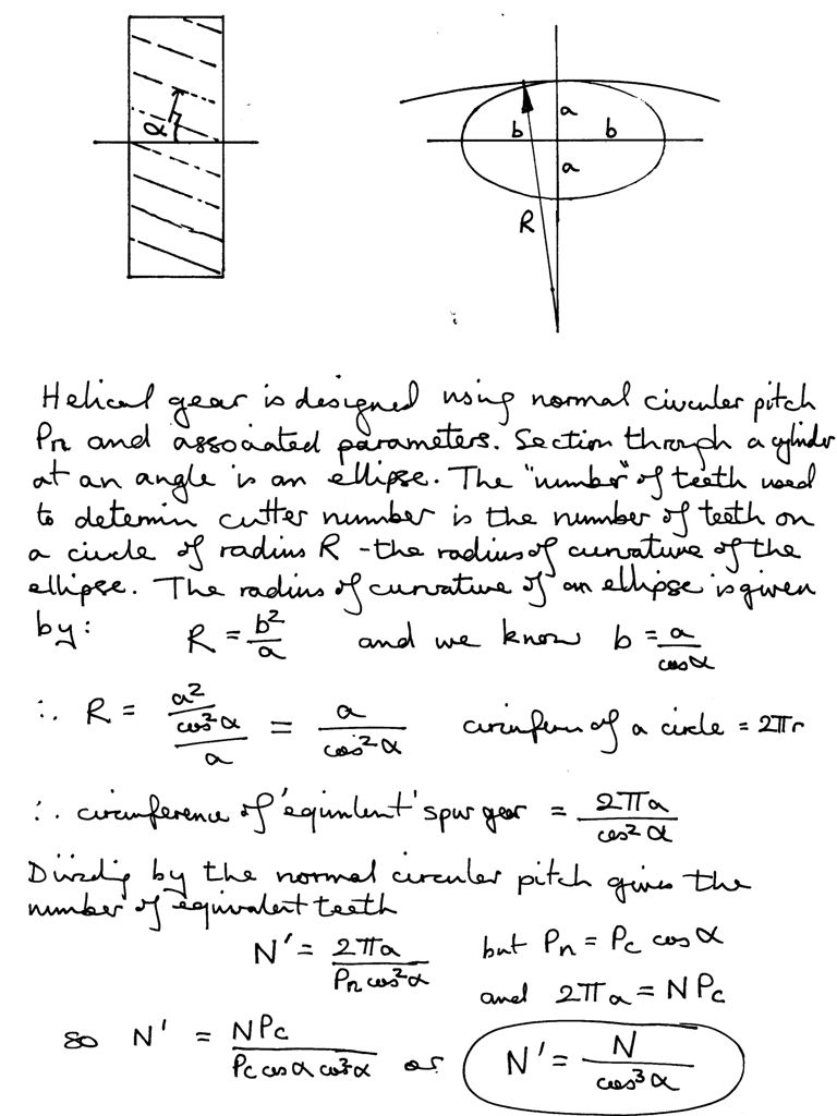
      I assume that anyone reading this thread has some interest in the subject matter, or is hopelessly lost, so I'll continue where the other threads left off by showing that the equivalent number of teeth used to select the appropriate involute cutter is given by the actual number of teeth divided by the cube of the cosine of the helix angle:

      number of equivalent teeth.jpg

      So far so neat, but at this point it all goes pear-shaped. There are inconsistencies in the literature as to when the above equation is valid, and what equations might replace it.

      I found one online book stating that N' is given by N divided by the square of the cosine, multiplied by the sine, both of the helix angle. The example given was for a helix angle of 45º, which of course works since cos(45º ) = sin(45º ). However, if we examine what happens at a helix angle of 0º, ie, a spur gear where N' = N, the equation blows up as sin(0º ) = 0. And division by zero is undefined. So I'm going to ignore that version of the equation.

      I have found two other variants. One, from Machinery's Handbook, adds a second term involving the tangent of the helix angle and the pitch diameter of the cutter. Another online source gives an equation that involves both the tangent of the helix angle and the helix angle itself.

      More notes on this will follow when I've had another look at the equations and made some sense of them. However my current thinking is that the corrections are needed because the involute tooth form, normal to the helix angle, which we assume lies in a plane does not in fact do so as a consequence of the helical path of the teeth.

      Andrew

      Edited By JasonB on 25/07/2015 20:39:56

      Advert
      #15795
      Anonymous
        #197984
        Michael Gilligan
        Participant
          @michaelgilligan61133

          Andrew,

          I am very pleased to see you addressing this matter … because I think that [of all those here] you are the one with the skill and tenacity to find the 'truth'.

          For what it's worth [i.e. not very much], I supect that you will come across rather a lot of 'convenient approximations' in your search for the underlying mathematics.

          …This definitely wants "a fresh dose of looking-at".

          MichaelG.

          #198006
          Anonymous

            I suspect that a lot of engineering theory is based on approximations. This was particularly true in the past before the advent of electronic calculators and computers. It is interesting to compare old and new engineering text books. Older books tend to analyse a series of basic problems, making approximations and deriving a solution, often graphical so it can be performed on a drawing board. Newer text books tend to be more mathematical and concentrate on the theory, assuming that any real world solutions will be done using a computer. The danger with that is GIGO.

            Problems arise when the approximations are not understood by the user. That is what interests me in the design process; how and why are equations derived and what are their limits of application.

            Coffee break over, back to machining!

            Andrew

            GIGO = garbage in, garbage out

            #198016
            Phil P
            Participant
              @philp

              Andrew

              I use one particular book for most of my gear calculations, it was passed down to me from my late father and I would not be without it. I have just googled the book and it is available to read online now.

              https://books.google.co.uk/books?id=x2GThADLN-sC&printsec=frontcover&source=gbs_ge_summary_r&cad=0#v=onepage&q&f=false

              Phil

              Edited By John Stevenson on 26/07/2015 14:31:32

              #198030
              Ajohnw
              Participant
                @ajohnw51620

                The Brown & Sharp treatise that is on the internet archive explains the reason for the approximations rather well. They add an approximation that seems to be based round their standard size gear cutters. Machinery's Handbook goes a little further according to Rod by adding an approximation based on the actual diameter of the cutter used.

                It all comes down to the fact that a circular form cutter is being used to cut the teeth. The profile of the cutter will be produced accurately at right angles to cutter but that isn't how the teeth will mesh with another gear in practice. There are several versions of a Practical Treatise on Gearing on the archive. The one I have is dated 1930. It's probably easier to read this one

                **LINK**

                This too uses screw cutting to explain the problem on the pages before the one this link may open to. If not the form tool problem is discussed around p102.

                surpriseSo Rod should use a single point lathe type form cutter plus gearing up his lathe to cut his gears as the form tool could then be put at the correct angle – wink Even more strain on his wrist.

                Maybe a hob can be used if it's at the correct angle to the gear being cut. I suspect that the angle would have to relate to the hob – gear ratio and both would have to be rotated at the correct rate. Not even going to think about it. I'm happy with approximations. There is a fair amount of that involved in cutting any gears with the usual circular form cutter any way – most of it derived via an add hoc approach – tried and it works.

                John

                #198046
                Roderick Jenkins
                Participant
                  @roderickjenkins93242

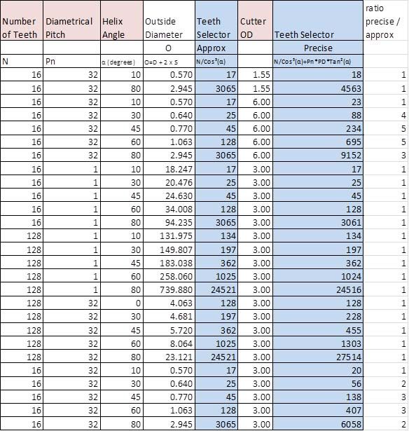
                  The method for milling gears, as opposed to hobbing, uses approximations as is demonstrated by the fact that each Brown and Sharp type cutter can cut a range of spur gears. However, the method appears to make perfectly acceptable gears. The choice of the correct cutter for helical gears, using the cos cubed rule also seems to work adequately, at least in some circumstances. If we assume that the "additional term" produces more accurate gears it is, perhaps, instructive to look at where the 2 methods of calculating the correct cutter differ.

                  hel table.jpg

                  Essentially there are 2 circumstances where the the additional term calls for a higher number cutter: Where the cutter has a large diameter compared to the gear blank and/or where there is a large helix angle. The results above beg another question: The Brown and Sharp cutter set assumes that for a spur gear anything above 135 teeth is considered to be equivalent to a rack i.e. the tooth form is essentially straight sided. My understanding is that the cos cubed rule and its extended version chooses a cutter with a higher number of teeth so that the cutter is narrower than otherwise and so does not cut a thinned tooth. In this case, surely, the 135 and above rule is invalid. Therefore, we really shouldn't be trying to cut a helical gear that calls for a cutter able to cut anything in excess of 135. As can be seen from the above table of random calculations; some gears call for teeth values of several thousand!

                  My interest in home made helical gears stems from making small i.c. engines which, unfortunately, tends to call for small diameter gears with small numbers of teeth – on the edge of what is possible.

                  I'm grateful for Maurice's OP that started discussion on this topic so thanks, chaps, for engaging – I hope Andrew can tease out the derivations and make my assumptions (in)valid.

                  Cheers,

                  Rod

                  #198055
                  Ajohnw
                  Participant
                    @ajohnw51620

                    The reason for one of the problems is easy to explain. Say a cutter at the correct helix angle is just plunged into the gear at the right place. The cutter will cut a straight line slot with a curved bottom. Directly below the cutters centre the form will be exactly the same as the cutter and the form required on the gear for a length of "zero". Simply put from now neglecting the depth cut away from the centre – Ahead of the centre line it will produce the same form but at points that are wider than the required tooth form on one side, same behind. As the work is then rotated and the cutter advanced in sync the cutter will only remove metal from one side and the sides will be opposite each other ahead and behind the cutter.

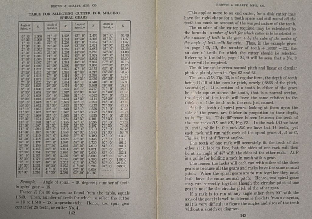
                    The Brown & Sharp book glosses over this by suggesting that the next finest DP should be used with circular cutters. The mention replacing 10 DP with 12.

                    spiralgearchartbrown&sahrp.jpg


                    They then go on and talk about hobbing with straight sided rack form cutters pointing out that all gears will mesh from the same rack and also the angle aspect I mentioned and wondered about. As with many books like this it's a bit jumbled.

                    This is in the 1929 version. The 1920 version on the archive does have some of this in it.

                    John

                    Edited By John W1 on 26/07/2015 20:52:37

                    #198061
                    Roderick Jenkins
                    Participant
                      @roderickjenkins93242

                      John,

                      I agree with that – the helix means that the cutter interferes, and you have explained it rather better than I did, which is why the larger diameter cutter has a greater effect. The cos cubed solution appears to overcome this by choosing a narrower cutter. However…

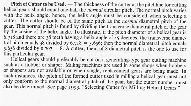
                      hg from mh.jpg

                      …seems to imply, as your post does, that one should use a cutter with different DP. This does not really seem to be a practical solution. It might, kind of, work for a pair of 45 degree gears but certainly will not for, say, a 60 and 30 degree pair. I've already fallen into this trap (sorry Diane!). The cos cubed method does seem to be a practical solution. None of the numerous sources I have consulted really seem to have a good understanding of the issues, let alone be able to explain it to the likes of me.

                      cheers,

                      Rod

                      The quote is from Machinery's Handbook 25, page 1985

                      Edited By Roderick Jenkins on 26/07/2015 22:31:39

                      #198065
                      Anonymous

                        Phil: Thanks for the link to the book. I first used it 40 odd years ago for an apprentice project that involved designing and making bevel gears. Subsequently I bought a copy, and it is my 'go to' book when designing and making gears.

                        John: Thanks for the link to the B&S book. I've had a quick read and they seem to give a good description of the problem, although the analysis is a bit lignt. However, that is not surprising as I suspect most people at the time left school at 13 or 14 with only a basic education. Thus a chart that could be read off was more useful than a equation.

                        There is plenty to think about so I'll need to trawl through the other posts and cogitate. I think I begin to see the problem, at least in my head. Translating that into words and an analysis is rather more difficult. I think the basic issue is that the tooth form follows a helicoid (I had to look it up too). The simple theory, using involute cutters, assumes that the tooth form of the cutter is based on an intersection of the helicoid and a plane. In reality I think that the tooth form required results from the intersection of two helicoids. So the adjustments and 'exact' formulae are basically trying to correct for the differences between the assumed, and real, intersections. Intuitively one would assume that if the basic helix angle is small, and the gear has a large number of teeth, then the errors are small, which seems to be the case?

                        As a slight aside the helix angle quoted is only valid at the pitch circle diameter. The helix angle at the root and apex of a tooth will be different. This leads to a question. I have sketched out the bare bones of a G-code program, using subroutines, for cutting a helical gear. Presumably each pass would need to use a different helix angle depending upon where it was cutting relative to the pitch circle diameter?

                        Andrew

                        #198066
                        Mark C
                        Participant
                          @markc

                          So Andrew, is this the result of your escapade with the steering gears – when you cut your own worm and wheel for the traction engine – floating about in your subconscious until it forced you to look deeper into gear cutting trigonometry?

                          Mark

                          Just found a link to this interesting bit of binary magic…. http://www.pressebox.com/pressrelease/gwj-technology-gmbh/Tooth-Contact-Pattern-Get-it-Fixed-Right-Away/boxid/531755 

                          Edited By Mark C on 26/07/2015 23:40:21

                          and just to help with the theory, I bumped into this little collection of snippets that might take a couple of lifetimes to sort and digest…. https://www.google.co.uk/search?q=contact+area+for+helical+gear&rlz=1C2GIGM_enGB628GB628&biw=1600&bih=771&tbm=isch&tbo=u&source=univ&sa=X&ved=0CDQQsARqFQoTCMaGiIXu-cYCFYVp2wodAKEGSg#tbm=isch&tbs=rimg%3ACXdZ-igUHzBEIjg8yngdv4o-RZL1-ODd2vNr_1-IuIAkYXQl4ZVVRELE-ce8kCH6mizVLAIQKlF2BMD3GpYF1sb_17TioSCTzKeB2_1ij5FEe-8oMmfRhs0KhIJkvX44N3a82sRDU6z5e72LqcqEgn_14i4gCRhdCRGuIfvCbLfxwioSCXhlVVEQsT5xEe-8oMmfRhs0KhIJ7yQIfqaLNUsRPoPvepDAiUwqEgkAhAqUXYEwPRG9MFRcy9G8bioSCcalgXWxv_1tOEX8NyOmw6-F5&q=contact%20area%20for%20helical%20gear sorry it is long but it was not the original search term that found it

                          Edited By Mark C on 26/07/2015 23:56:11

                          #198068
                          Ajohnw
                          Participant
                            @ajohnw51620

                            The B&S book does use the statement along the lines of the best that can be expected in a workshop relating to using disk type form cutters.

                            The various versions that are about suggest that what is probably needed is a circa 1950 edition. It might give a better explanation. I'll have another look tomorrow and see if it expands on using a finer cutter.

                            When I see info laid out like this I always wonder why they don't just add one clear and complete worked example rather than tooing and froing. wink but in some areas where that is common the methods often don't work for anything other than the example.

                            John

                            #198069
                            Ajohnw
                            Participant
                              @ajohnw51620
                              Posted by Andrew Johnston on 26/07/2015 23:18:36:

                              Phil: Thanks for the link to the book. I first used it 40 odd years ago for an apprentice project that involved designing and making bevel gears. Subsequently I bought a copy, and it is my 'go to' book when designing and making gears.

                              John: Thanks for the link to the B&S book. I've had a quick read and they seem to give a good description of the problem, although the analysis is a bit lignt. However, that is not surprising as I suspect most people at the time left school at 13 or 14 with only a basic education. Thus a chart that could be read off was more useful than a equation.

                              There is plenty to think about so I'll need to trawl through the other posts and cogitate. I think I begin to see the problem, at least in my head. Translating that into words and an analysis is rather more difficult. I think the basic issue is that the tooth form follows a helicoid (I had to look it up too). The simple theory, using involute cutters, assumes that the tooth form of the cutter is based on an intersection of the helicoid and a plane. In reality I think that the tooth form required results from the intersection of two helicoids. So the adjustments and 'exact' formulae are basically trying to correct for the differences between the assumed, and real, intersections. Intuitively one would assume that if the basic helix angle is small, and the gear has a large number of teeth, then the errors are small, which seems to be the case?

                              As a slight aside the helix angle quoted is only valid at the pitch circle diameter. The helix angle at the root and apex of a tooth will be different. This leads to a question. I have sketched out the bare bones of a G-code program, using subroutines, for cutting a helical gear. Presumably each pass would need to use a different helix angle depending upon where it was cutting relative to the pitch circle diameter?

                              Andrew

                              If the cutter that is producing the form on a helix is sufficiently small compared with the form it's some how cutting the error will be correspondingly small. That's why the B&S page I photo'd mentions that the table is only really appropriate for a end mill with the correct form on it. It seems that these were available in the past.

                              John

                              #198213
                              Tendor
                              Participant
                                @tendor

                                This may help? See this link at the bottom of page 3.10.

                                **LINK**

                                It gives the cos^3 expression, indicating it to be an approximation, and then gives the "accurate" expression in terms of the involute function (tan(x) – x), where both helix angle and pressure angle come into play. No mention of the size (PD) of the cutter.

                                #198221
                                Anonymous

                                  Mark C: Not directly; sadly there are no helical gears on the traction engines. This particular wild goose chase was kicked off by the query about poor quality helical gears elsewhere on the forum. I just happen to like gears, so it kicked off curiosity as to the design of helical gears. I'm tempted to have a go at making some helical gears, just for fun. As far as the traction engines go the only gears left to make are the two bevel gears on the governor. After that I'll have to get down to boring stuff like the wheels. sad

                                  Rodney: Thanks for the link. I've bookmarked the page for future reference, and I've even contemplated buying the book. The equation quoted neatly illustrates the issue. As you say it doesn't involve the cutter at all, but other sources say you definitely need to include the cutter details. Which is 'correct'?

                                  Rod: I'm not sure I understand your point about a thinner cutter? As far as I know all the involute cutters in a given set have the same width at the PCD. Of course the cutter thickness will vary above and below the PCD according to the curvature of the involute. I haven't seen anything yet that implies using a cutter of a different DP to that designed for; although I've only skimmed a lot of literature so far. I assume that part of the design process ensures that normal DP is a nice round number and the linear DP will be what it is, rather than vice-versa. Without looking at the equations in detail I'd take a WAG and say that the corrections to the one over cos cubed term increase the number of equivalent teeth; thus tending to flatten out the tooth form to one that is more rack like.

                                  Now back to work!

                                  Andrew

                                  WAG = Wild a*s guess – not what you thought it was, I can't afford those!

                                  #200511
                                  Roderick Jenkins
                                  Participant
                                    @roderickjenkins93242
                                    Posted by Andrew Johnston on 28/07/2015 11:51:36:

                                    Rod: I'm not sure I understand your point about a thinner cutter? As far as I know all the involute cutters in a given set have the same width at the PCD. Of course the cutter thickness will vary above and below the PCD according to the curvature of the involute. I haven't seen anything yet that implies using a cutter of a different DP to that designed for; although I've only skimmed a lot of literature so far. I assume that part of the design process ensures that normal DP is a nice round number and the linear DP will be what it is, rather than vice-versa. Without looking at the equations in detail I'd take a WAG and say that the corrections to the one over cos cubed term increase the number of equivalent teeth; thus tending to flatten out the tooth form to one that is more rack like.

                                    Yes, of course (silly me!), you are correct about the PCD. I also agree with your comments about the relationship between normal and linear DP. In effect, a gear must be defined by the hob that makes it. My understanding now is that:

                                    A 32 DP hob makes a 32 DP helical gear; whatever the helix angle. By analogy the circular milling cutter makes a helical gear whose tooth form needs modifying to be the same as that which would be generated by the hob – this is achieved by the cos cubed term which produces, as you say, a more rack like tooth. The additional term compensates for the interference of the circular cutter away from the tangential point of contact.

                                    My guess is that if making a pair of gears then it is sufficient to use the cos cubed term alone. If the milled gear is required to mesh with a hobbed gear then the additional term should be used for best matching. Be wary of making a gear that call for a cutter of more than 135 teeth.

                                    In practice, it doesn't seem to matter too much. Chuck Fellows and I have both made satisfactory gears for driving i.c. cam shafts using the cos cubed term alone (Chuck originally used the graph from Colvin and Stanley – Gear Cutting Practice and, I've checked, it's calculated on Cos cubed alone). But, and it's a big but, I would like to understand the derivation of the various calculations so that I know which ones can be safely ignored.

                                    Still hoping,

                                    Rod

                                    #200742
                                    Anonymous

                                      It is proving quite difficult to separate the exact and approximate. I think that most of what has been discussed so far is approximate, including the cos cubed adjustment. There is also a need to distinguish between approximations in the mathematical description, and those due to the machining process.

                                      To be exact the tooth form on a helical gear follows a helicoid. Therefore the normal to the tooth form is also a helicoid, not the plane which we have been discussing thus far. The cos cubed approximation assumes that the normal is a plane. A sensible place to start seems to be understanding the tooth form. I make the assumption that the transverse tooth form, ie, looking along the axis of rotation of the gear, is a true involute and, since the end of the gear is presumably flat, is defined on a plane. It is interesting to note that as this true involute is mapped onto a plane normal to the helix angle not only does the DP change, so does the pressure angle. Another point to note is the helix angle only applies at the PCD of the helical gear. The helix angles at the root and crest of the tooth are different, the helix angle decreasing as the diameter decreases and vice versa.

                                      So making a bit of a jump I think it means that forming a helical gear with a standard involute cutter can never be exact. I think the same is true for a hob, as it can only be set to one helix angle? In theory it should be possible to make a more precise helical gear using a small diameter cutter and a 4-axis CNC mill, where the helix angle can be varied slightly according the depth of cut relative to the PCD.

                                      I have had a brief conversation with Chuck Fellows on another forum and he kindly posted his Excel spreadsheet, which uses the cos cubed correction.

                                      I agree with Rod that most of this discussion doesn't matter in practical terms for the sort of lightly loaded and low speed gears we are likely to make.

                                      Andrew

                                      #200749
                                      Michael Gilligan
                                      Participant
                                        @michaelgilligan61133
                                        Posted by Andrew Johnston on 17/08/2015 11:11:02:

                                        … I agree with Rod that most of this discussion doesn't matter in practical terms for the sort of lightly loaded and low speed gears we are likely to make.

                                        .

                                        Of course not, Andrew … But please keep up the good work. star

                                        Like Jazz Musicians and Circus Clowns: You need to understand the rules before you can play about.

                                        MichaelG.

                                        #200761
                                        John Stevenson 1
                                        Participant
                                          @johnstevenson1
                                          Posted by Michael Gilligan on 17/08/2015 11:41:00:

                                          Like Jazz Musicians and Circus Clowns: You need to understand the rules before you can play about.

                                          MichaelG.

                                          .

                                          Are they not one and the same ?

                                          #200786
                                          Michael Gilligan
                                          Participant
                                            @michaelgilligan61133
                                            Posted by John Stevenson on 17/08/2015 12:53:27:

                                            Posted by Michael Gilligan on 17/08/2015 11:41:00:

                                            Like Jazz Musicians and Circus Clowns: You need to understand the rules before you can play about.

                                            MichaelG.

                                            .

                                            Are they not one and the same ?

                                            .

                                            Good job I didn't include Bodgers in that list … it might have spoiled your fun.

                                            I'm sure that you, John, know [better than the rest of us] that the reason you can 'bend the rules' so effectively is because you understand them.

                                            MichaelG.

                                            #206895
                                            Anonymous

                                              I am in the process of tying up a few loose ends, and that includes this thread (pun intended). As far as I'm concerned this thread is now dead. I am still playing with the maths and intend to make some helical gears, but I'm afraid that I've run out of the enthusiasm needed to collate the information into a form suitable for posting.

                                              If anyone else wants to take up the mantle that's fine by me.

                                              Andrew

                                              #207050
                                              Ian S C
                                              Participant
                                                @iansc

                                                Andrew, you'v probably seen them, Chuck Fellows has just done a pair of helical gears on the MEM site, with a bit of description on how its done.

                                                Ian S C

                                                #207059
                                                Anonymous

                                                  Thanks; I have seen the work by Chuck, talked to him about them and downloaded his calculation spreadsheet. He uses the cos cubed method to determine the equivalent number of teeth. Clearly that works fine in the application, and his gears look great. But, while it probably isn't critical for ME applications, I want to delve further into the theory and manufacturing methods. That probably puts me in a minority of one.

                                                  Andrew

                                                Viewing 23 posts - 1 through 23 (of 23 total)
                                                • Please log in to reply to this topic. Registering is free and easy using the links on the menu at the top of this page.

                                                Advert

                                                Latest Replies

                                                Home Forums Workshop Techniques Topics

                                                Viewing 25 topics - 1 through 25 (of 25 total)
                                                Viewing 25 topics - 1 through 25 (of 25 total)

                                                View full reply list.

                                                Advert

                                                Newsletter Sign-up