Faceplate mounting on a horizontal mill (Centec 2a)

Faceplate mounting on a horizontal mill (Centec 2a)

Home › Forums › Manual machine tools › Faceplate mounting on a horizontal mill (Centec 2a)

Viewing 24 posts - 1 through 24 (of 24 total)
  • Author
    Posts
  • #714103
    Henry Bainbridge
    Participant
      @henrybainbridge40560

      I just saw this video: https://www.youtube.com/watch?v=0znLGi_fCcg and wanted to do something similar.

      I need to turn the edges and face off a 14″ alu turntable platter. I don’t have a lathe big enough but I have a Centec 2a with a 30 INT taper.

      How advisable is this, and if not ill-advised, what would be the best way to go about it? Anything I should bear in mind?

      #714122
      DC31k
      Participant
        @dc31k

        Many a horizontal mill has been used as a lathe in the past. Nothing wrong with the concept when used with care.

        Will 7″ fit between the spindle centre and the top of the Y-axis dovetail on the knee with the knee at its lowest?

        What is the slowest speed at which the mill will turn? Does that give a slow enough surface speed at 14″ diameter?

        It will need a good riser block to bring the cutting tool up to centre height.

        Having the 30 taper will in some respects be a better starting place than the other option of 2 Morse (larger, stiffer).

        Having the 30 taper will in some respects be a more difficult starting place than the other option of a 2 Morse. A 2 Morse to Myford thread arbor is cheap and allows easy mounting of pre-existing chuck or faceplate.

        It is difficult to find the equivalent of a soft, blank arbor in 30 taper. For a one off, maybe put an ER40 chuck in the mill taper and then make a straight-shank adaptor suitable for your chosen faceplate or chuck.

        You might have to make a 30 taper shaft and weld a round plate to it to make a faceplate. Truing it up will be a test run before you bolt the aluminium to it for the real job.

        If you find a 30 taper to D1-3 adaptor on your travels, please pick one up for me.

        If the mill-as-lathe does not work out, it might be possible to use a horizontal rotary table powered by a cordless drill and a flycutter in the vertical head for facing (the finished surface would look as if it had been Blanchard ground). The difficulty would be the 3 1/2″ radius (7″ diameter) that the flycutter would need to sweep without hitting the column of the mill.

        #714180
        Nigel Graham 2
        Participant
          @nigelgraham2

          Since the tool would need be high enough to reach the work centre while the knee is still below the rim of the disc, do you have a rear tool-post for your lathe? If so, that may solve the problem provided you can fit it to the Centec table satisfactorily. (That for the Myford lathe, for example, has a tenon on its base, which may not fit a Centec Tee-slot.)

          Alternatively, make a tool-holder by milling a channel along a steel, cast-iron or indeed aluminium-alloy block provided with appropriate tapped holes; one set for screws securing the tool in the channel, the others for fastening the block to an angle-plate.

          .

          Regarding using a fly-cutter with the plate on a rotary-table, I would take this in two or more stages by moving the table longitudinally between complete RT rotations, so the cutter does not need a full 7″ diameter sweep. That is a massive sweep for a fly-cutter on a small machine, would put considerable strain on it, and could give poor results.

          Power-driving the rotary-table is not essential but would give a constant feed-rate hard to achieve by hand, giving a much better surface finish. Would a cordless drill in direct drive be too fast? I have not tried it, but it may work on a screwdriver setting.

          The RT need not be centred to the spindle for facing (as it would for milling any additional features of course) as long as the innermost area is still swept by the cutter.


          #714185
          Henry Bainbridge
          Participant
            @henrybainbridge40560

            That’s great news, thanks! The plan is to mount a spare Dickson tool post on a 5” riser, giving just over 7.5” between horizontal spindle centre and top of knee dovetail. The riser will have a central bore for some threaded bar to both keep the riser in place with a T nut on the bottom end and hold the tool post down with the usual hex nut at the top.

            For extra stability a .2 inch deep tenon will be machined in the base which can slide along the T slot of the table as suggested. I do have a rear tool post which I considered using but it’s a bit too short and I need something a little more versatile for some features I am planning.

            I have an old faceplate that doesn’t fit my lathe so I have rebored it and cut a new internal thread to fit an existing threaded 30 INT shank. I will fix the platter to the faceplate with some bolts threaded straight through from the back, ensuring they don’t go all the way through of course, as I need to face the entire surface in one pass ideally.

            I think the slowest the Centec will do is 40rpm, so I will start there. Hopefully I can find a speed that will work well across all 7 inches, as I can’t change gear on the fly. I have powered table feed on the x axis though, so hopefully it should look pretty neat.

            This is for a vinyl lathe project so accuracy is important. If there is too much runout I might have to go the RT route but I will cross that bridge if I come to it. Thanks again!


            #714197
            DC31k
            Participant
              @dc31k
              #714204
              DC31k
              Participant
                @dc31k
                #714233
                Dave Halford
                Participant
                  @davehalford22513

                  Slowest speed is 85rpm – note the smoke coming off the carbide cutter from the cast iron in the video at the start disappears nearer the centre. + he is turning smaller that 14″.

                  That said you need to turn alloy so should be about the same.

                  A lenco turntable for example would have a spindle right through the platter. You could turn up an adapter shaft to fit the spindle hole from  2″ round steel stock leave a 1/4″ thick flange and make a 5/8″ or 16mm spigot to fit into your milling cutter holder. Glue it to the table and feed light and slow. Remove with blowlamp when done.


                  #714248
                  Henry Bainbridge
                  Participant
                    @henrybainbridge40560
                    #714260
                    DC31k
                    Participant
                      @dc31k

                      The boring head adaptor in 30 taper is listed by RDG.

                      Maybe approach the faceplate undoing with a suck-it-and-see attitude. Disconnect the reverse switch so that problem goes away.

                      Mount just the faceplate, spin it up way faster than you will do when turning the part and try to stop it quick and make it unscrew itself. Bolt some lumps of metal to its perimeter to amplify the problem.

                      If your extreme torture tests do not produce a bad result, then nor will more sedate use of it. Loctite the faceplate to the arbor.

                      #714263
                      Henry Bainbridge
                      Participant
                        @henrybainbridge40560
                        #714292
                        Bazyle
                        Participant
                          @bazyle

                          If the Centec has backgear don’t be playing games with sudden stops or you might lose some of the bull wheel teeth. Unlike a lathe the gears will not be built for high strength. Better to mount a bicycle wheel on the back of the shaft and drive it slow off another motor.
                          You shouldn’t be using a reversing switch for on/off. When the contacts burn out it will be much more expensive to replace or repair. Get an NVR switch.

                          #714299
                          Henry Bainbridge
                          Participant
                            @henrybainbridge40560

                            Just to clarify, the reverse switch is essential because the vertical spindle is connected to the horizontal spindle via a mitre gear… so it goes the wrong way unless you reverse it.

                            I never suggested using the reverse switch to force a sudden stop, I am saying the suggestion of another level of safety is welcome, since there is a small chance that the machine may be powered up in reverse by mistake.

                            #714311
                            old mart
                            Participant
                              @oldmart

                              For maximum stiffness, I would look at a MT 3 socket outside diameter for the boss of the faceplate. The OD of the socket projects a good ammount and is cylindrical, and it might be possible for a custom drawbar shank to project right through the centre for holding the plate securely.

                              The suggested boring head adaptor would be a possibility for attaching the plate if you can put a compatible thread in the plate.

                              #714383
                              Tendor
                              Participant
                                @tendor

                                My effort to use a ‘faceplate’ on a NT30 spindle may trigger some thoughts.

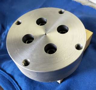
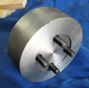
                                The nose dimensions and tolerances of the four threaded holes, and the spindle diameter, are well defined.  I have used the four cap screws as retainers and the OD of the spindle nose as the radial locator. It has been used to date to mount a four-jaw chuck.

                                Front NT30 adaptor

                                Rear NT30 adaptor

                                #714398
                                DC31k
                                Participant
                                  @dc31k
                                  #714439
                                  Henry Bainbridge
                                  Participant
                                    @henrybainbridge40560
                                    #714446
                                    Henry Bainbridge
                                    Participant
                                      @henrybainbridge40560
                                      #714451
                                      DC31k
                                      Participant
                                        @dc31k

                                        “Not sure what that means, would be interested to see.”

                                        Page 80 and page 92 here:

                                        https://archive.org/details/treatiseonmillin00cincrich/mode/2up

                                        The whole book is superb. Their ‘Treatise on planers’ is also highly recommended.

                                        There is another ‘Treatise on milling’ by Brown & Sharpe which might also show some.

                                        #714677
                                        Henry Bainbridge
                                        Participant
                                          @henrybainbridge40560

                                          That’s a great book, beautifully put together, thanks for the link.

                                          Those bolt holes seem to have fallen out of use so it seems strange they are still included in new milling machines today, or am I missing something? I haven’t seen any tooling that obviously use them, and wouldn’t know what to search for if I wanted to. Anyway, they will definitely come in handy for this application!

                                          #714691
                                          Anonymous

                                            I considered using this technique some years ago when I was asked about a job that needed a 36″ diameter disc to be turned. Ultimately the job disappeared so I never used the technique. But it’s a useful idea to have in the armoury.

                                            In answer to Henry I have used the four holes (threaded 1/2″ BSW) on my INT40 vertical head for the horizontal mill to mount a large (160mm diameter) insert cutter.

                                            Andrew

                                            #715501
                                            Henry Bainbridge
                                            Participant
                                              @henrybainbridge40560

                                              I am wondering, did the cutter have the int40 taper, or did it just use the bolts and locate against the face?

                                              #715551
                                              DC31k
                                              Participant
                                                @dc31k
                                                #715589
                                                Henry Bainbridge
                                                Participant
                                                  @henrybainbridge40560

                                                  Brilliant, just the info I need. So it looks like all bolt-mounted cutters use a centering plug, and larger cutters achieve added rigidity from the outer diameter of the spindle. A large faceplate definitely falls into this category, so I should be using both.

                                                  The pdf doesn’t give the spec for a 30 int centering plug, but they are available with a 1″ arbor (by Jones & Shipman) so I am going with that. I think the idea is that the drawbar keeps the plug in place, and the cutter just slides onto it (and the outside of the spingle nose) and is drawn in by just the 4 bolts. This makes sense, as I was wondering how it could locate on the taper and the face at the same time… the answer is it doesn’t.

                                                  Come to think of it, it might be hard to make an adaptor that centers on the plug and the outside of the spindle. I am relying on them being perfectly concentric… I guess I will cross that bridge when I come to it!


                                                  #715601
                                                  Anonymous
                                                  Viewing 24 posts - 1 through 24 (of 24 total)
                                                  • Please log in to reply to this topic. Registering is free and easy using the links on the menu at the top of this page.

                                                  Latest Replies

                                                  Home › Forums › Manual machine tools › Topics

                                                  Viewing 25 topics - 1 through 25 (of 25 total)
                                                  Viewing 25 topics - 1 through 25 (of 25 total)

                                                  View full reply list.