do i need reverse

Advert

do i need reverse

Home Forums General Questions do i need reverse

Viewing 21 posts - 76 through 96 (of 96 total)
  • Author
    Posts
  • #186667
    Les Jones 1
    Participant
      @lesjones1

      Hi Kevin,
      Before giving you a diagram of how to connect the switch I want you to do some tests to confirm that the switch behaves as I expect from the diagram. First confirm that contacts 1 & 2 and 7 & 8 are closed in only one position and the same position of the switch. (Fully clockwise or fully anticlockwise.) And that contacts 3 & 4 and 5 & 6 are closed on the opposite position of the switch. (Let me know which way round this is.) Also confirm that the two contacts sets C & C on each side of the switch are closed in both the clockwise and anti clockwise position of the switch and they are two separate sets of contacts. one set on the side with terminals 1,2,3,4 and the other on the side with terminals 5,6,7,8 Which position clockwise or anticlockwise do you want to be forward ?

      Les

      Advert
      #186669
      kevin large
      Participant
        @kevinlarge76611

        Hi les
        am I looking for continuity between them
        dumb question I know

        1_2 and7_8 anticlockwise

        3_4 and 5_6 clockwise 

        C C are closed both ways

        C C 2sets

        Forward clockwise please

        Kevin

        Edited By kevin large on 16/04/2015 19:10:22

        #186693
        Les Jones 1
        Participant
          @lesjones1

          Hi Kevin,
          Can you confirm that your new switch already has metal straps between 2 & 4, 8 & 6, 3 & 7, and 1 & 5 ? From looking closely at Ketan's an your photos this looks to be the case. Do the terminals take push on connectors and if so does each terminal one or two push on connectors. ?

          Les.

          #186706
          kevin large
          Participant
            @kevinlarge76611

            Hi les yes to all the straps and it’s single push on connection
            kevin

            #186718
            Les Jones 1
            Participant
              @lesjones1

              Hi Kevin,
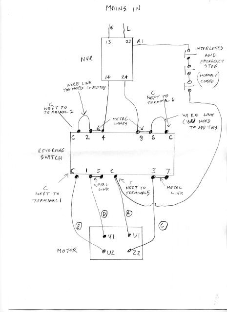
              Before you wire the switch as in the diagram below confirm the following.

              1 That there are no links on the opposite side of your switch to the one in your picture of the switch
              2 That the connections between the "C" contacts are between the (C next to terminal 1 and the C next to terminal 2) and (C next to terminal 5 and the C next to terminal 5) Also confirm these contacts are only closed in the clockwise and anticlockwise positions and not in the middle position.
              3 Confirm there is no contact between the "C" terminal next to terminal 1 and the "C" terminal next to terminal 6 in any position of the switch

              kevin001 (custom).jpg

              You will need to find a way to connect two wires to the "C" terminal next to terminal 5 You may be able to use an eyelet connector on one of the wires on the screw for that terminal or use a piggy back push on connector.

              If there is anything on the diagram you don't understand ask. If you don't understand the diagram would you like it in the form of a list of instructions. If you would like a higher resolution scan of the diagram than can be put on this forum then PM me with your email address and I can send it to you
              Make sure you do not disconnect any earth wires and if you mount the NVR switch and/or the reversing switch in a metal box make sure it is earthed.

              Les.

              #186734
              Nicholas Farr
              Participant
                @nicholasfarr14254

                Hi Les, I did a diagram last evening, using the information from Ketan's and Kevin's photos, which has the same result, albeit wiring it a different way, but I may have the F/R positions the opposite way round, although swapping a couple of wires will put it the same. I haven't included the interlocks or the A-D wire designations that you have as I gathered you would set it out in a way that Kevin should be able to follow OK. You can see my diagram here if you wish **LINK**. I've only done it to see if I could get much the same result as yourself.

                Regards Nick.

                Edited By Nicholas Farr on 17/04/2015 13:24:37

                #186749
                Les Jones 1
                Participant
                  @lesjones1

                  Hi Nick,
                  I agree. There are a few variations that could be done to achieve the same result. I think we have both got forward and reverse the way Kevin wants it. (If it was for myself I would not bother working it out. I would have just reversed two wires if it was wrong.) I was wrong in my post on the 16th at 12:20 when I said that I thought the new switch only had one pole to isolate the main winding. It is a strange coding system with four terminals being labelled "C" I have taken the live feed to the maintainer coil in the NVR via one set of "C" contacts so if the reversing swtch is moved through the centre position it will cause the NVR to drop out. I did think of suggesting that Kevin labelled the switch end of the motor cable with A to D but decided it might cause confusion in the future with someone thinking wire C should go to terminal C.

                  Les.

                  #186752
                  kevin large
                  Participant
                    @kevinlarge76611

                    Hi les and nick first I would like to thank you both very much for all your help it looks like the switch will fit nicely in the original place with a little bit of work need to decide best place for the var probably won't get time before going on holiday for a week I have put a PIC on of var so you can see the one I've got and it ties in with wiring diagram

                    Thanks again Kevinvar

                    Edited By kevin large on 17/04/2015 16:02:00

                    #186757
                    Les Jones 1
                    Participant
                      @lesjones1

                      Hi Kevin,
                      That NVR switch looks fine. Would there be room to fit it on a panel with the new reversing switch with the supplied knob rather than adapting it to work with the existing lever. You will be using the buttons on the NVR far more than the reversing switch. I very rarlly use reverse on my lathe. I would suggest making a new panel rather than modifying the old one.

                      Enjoy your holiday.

                      Les.

                      Edited By Les Jones 1 on 17/04/2015 17:28:41

                      #186766
                      Nicholas Farr
                      Participant
                        @nicholasfarr14254

                        Hi Les and Kevin, Les I think it is very prudent the way you have connected the maintainer coil and I think I would have done it in much the same way, because although the new switch can handle the electrics, I don't think the new switch is physically robust enough for the constant use that the lever would put on it and it may not stand the starting load for very long when used in the same manner as the original one.

                        I have purchased the other switch that Ketan showed in his photos, it is pre linked the same, although the switch on mine is still working, my machine is getting on a bit and now I have a replacement if it should fail.

                        As far as mounting the new switch, it would be possible to mount a box to hold the switch and the NVR, where the lever is fitted, but due to the length of the switch it will be a bit sticky out. I think it would be better to fit it in the original hole and make a plate for the new switch big enough to pick up the bolt holes that held the lever in place, but then Kevin would probably have to mount his NVR in a suitable box and mount it in an appropriate place. He may be able to fix the box somewhere close to the new switch, but will have to be a choosey where to drill new holes for fixing it.

                        Regards Nick.

                        #186796
                        kevin large
                        Participant
                          @kevinlarge76611

                          Hi les
                          I was just wondering if the NVR has an emergency stop and I don’t have the interlocks do I need the wire c to a1
                          kevin

                          #186797
                          Les Jones 1
                          Participant
                            @lesjones1

                            Hi Kevin,
                            You need the wire from C (Next to terminal6) to A1 for the NVR switch to remain on after pressing the start button. Anything that breaks that connection caused the NVR to drop out. At the moment just wire in the emergency stop button. (The contacts on this will be closed until it is pressed) You can add any number of interlocks in the future. If you do not even want to wire in the emergency stop button then just link from C (Next to terminal6) to A1 for the NVR switch

                            Les.

                            Edited By Les Jones 1 on 18/04/2015 08:56:57

                            #186854
                            kevin large
                            Participant
                              @kevinlarge76611

                              Hi les and nick you will be glad to know lathe is working perfectly thanks guys could not have done without you thanks again just have to master cutting threads on it next
                              kevin

                              #186872
                              Les Jones 1
                              Participant
                                @lesjones1

                                Hi Kevin,
                                Now you can relax on holiday rather than worrying about getting your lathe working.

                                Les.

                                #186901
                                Nicholas Farr
                                Participant
                                  @nicholasfarr14254

                                  Hi Kevin, pleased we have helped you get your lathe running properly, but I think most of the credit should go to Les for helping you check your connections ect.

                                  Hope you enjoy your holiday.

                                  Regards Nick.

                                  #186939
                                  Les Jones 1
                                  Participant
                                    @lesjones1

                                    Hi Nick,
                                    If you had not posted the schematic of how the switch should have been wired and us noticing that the links we could see on the switch appeared to confirm that it was wired to this schematic I would not have has the confidence that I could talk Kevin through tracing how it was wired. Without that information I think I may have abandoned attempting to help Kevin.

                                    Les.

                                    #187026
                                    Raymond Sanderson 2
                                    Participant
                                      @raymondsanderson2

                                      Just following this as I have an ML7 reveres switch NOT usual type but similar to fit and considering maybe sourcing a newer type more compact and easier to fit…….maybe.

                                      #187050
                                      Les Jones 1
                                      Participant
                                        @lesjones1

                                        Hi Raymond,
                                        A Myford owner admitting to having a reversing switch other than a "Dewhurst" I thought that was against their religion or some unwritten law. (I'm sure JS will know the details.) Back to being sensible. Although the two switches That Arc Euro Trade sell are suitably rated they may possibly not be suitable for switching under load as seems to be the case on a lot of Myfords. They only seem to have the reversing switch. I would recommend fitting an NVR switch or proper motor starter for stopping and starting the lathe and just operate the reversing switch when the motor is stopped.

                                        Les.

                                        #187175
                                        Raymond Sanderson 2
                                        Participant
                                          @raymondsanderson2

                                          Posted by Les Jones 1 on 20/04/2015 09:18:09:

                                          Hi Raymond,
                                          A Myford owner admitting to having a reversing switch other than a "Dewhurst" I thought that was against their religion or some unwritten law. (I'm sure JS will know the details.) Back to being sensible. Although the two switches That Arc Euro Trade sell are suitably rated they may possibly not be suitable for switching under load as seems to be the case on a lot of Myfords. They only seem to have the reversing switch. I would recommend fitting an NVR switch or proper motor starter for stopping and starting the lathe and just operate the reversing switch when the motor is stopped.

                                          Les.

                                          Hi Les

                                          Yes i should hang my head in shame I know but at $25 it was a bargain having seen them on ebay at $150+ ouch. It wa suggested a NVR switch be fitted by the President of Hornsbey Model Rail club after he did work out wiring set up for the switch and motor I have fitted which was on the lathe when I purchased it.

                                          To me the NVR will be the better install for my use and space.

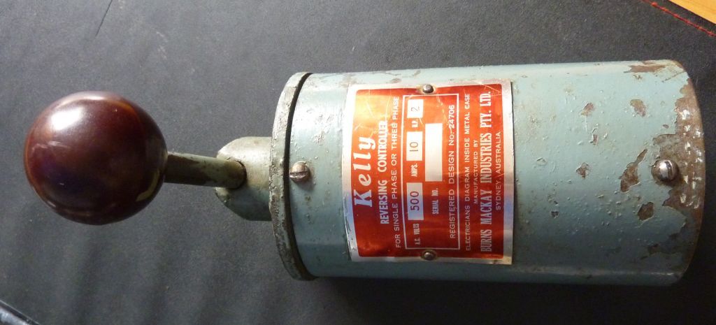
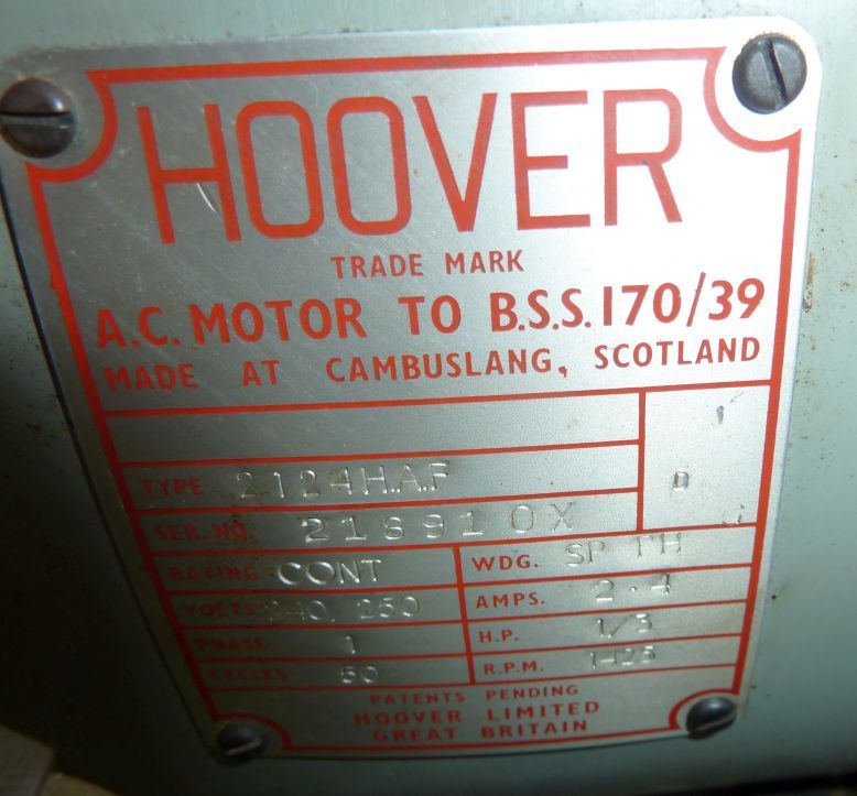
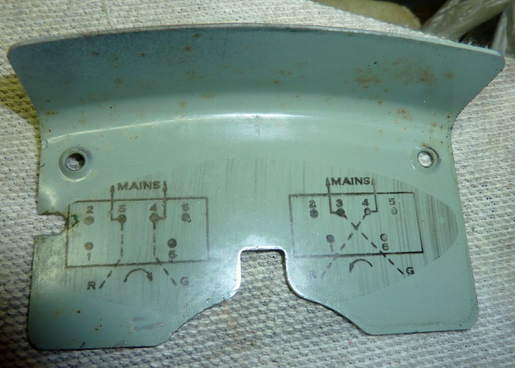
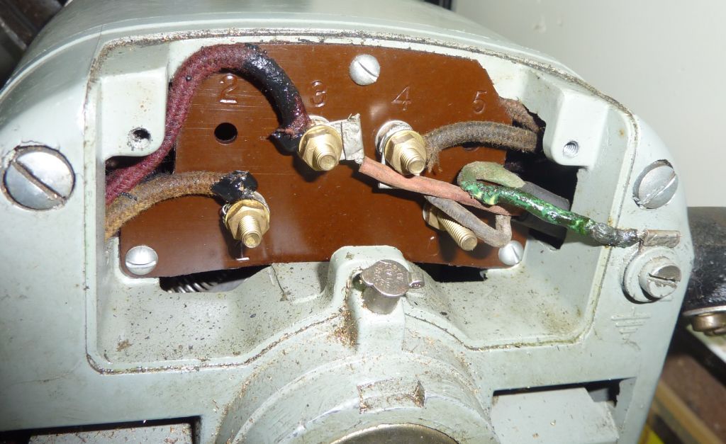
                                          Here are photos of the switch (I'll take one with it open latter) the motor and info on it.

                                          If I am hijacking this thread I apologise happy to have it moved.

                                          p1070924.jpg

                                          p1070949.jpg

                                          p1070952.jpg

                                          p1070954.jpg

                                          #187191
                                          Les Jones 1
                                          Participant
                                            @lesjones1

                                            Hi Raymond,
                                            The thread had come to an end as Kevin's new reversing switch from Arc Euro Trade is fitted and working. I was not sure yesterday if you already had a working reversing switch fitted and working but just thought it would be a good idea to have a spare to hand. If it is a question on how to connect the reversing switch in your picture or one similar to the two types that Arc Euro Trade stock then starting a new thread is probably a good idea to save people having to wade through all the questions and answers which are not relevant to your question. If you do want to know how to wire a reversing switch could you give me some idea of your level electrical knowledge. For example can you read a wiring diagram. Do you have a multimeter and know how to use it.
                                            Like J.S I find it amusing that a lot of Myford owners treat their late more like a museum exhibit than a tool. They must be painted exctly the right colour, they must have a "Dewhurst" reversing switch and they will not make any modifications that involves drilling holes.

                                            Les.

                                            #187218
                                            Raymond Sanderson 2
                                            Participant
                                              @raymondsanderson2

                                              Thanks Les I'll look into the new NVR take full photos of the Kelly switch.

                                              I am proud to own the ML7 it has had 3 previous owners two clock makers and a model engineer who stepped up to a larger lathe.
                                              My Ml7 is in a well kept order by those before me and paint work although has some chipped areas these are minor. I shall try my best to improve it but it may take drilling holes. I do cover mine clean it, oil it and am still slowly learning more of it each time I do use it.

                                              I can say in defence of Myford owners and the love they have for their machines its worth it unlike some of the newer cheap lathes produced these days. Much easier to pass onto a true enthiuseist.

                                            Viewing 21 posts - 76 through 96 (of 96 total)
                                            • Please log in to reply to this topic. Registering is free and easy using the links on the menu at the top of this page.

                                            Advert

                                            Latest Replies

                                            Home Forums General Questions Topics

                                            Viewing 25 topics - 1 through 25 (of 25 total)
                                            Viewing 25 topics - 1 through 25 (of 25 total)

                                            View full reply list.

                                            Advert

                                            Newsletter Sign-up