do i need reverse

Advert

do i need reverse

Home Forums General Questions do i need reverse

Viewing 25 posts - 51 through 75 (of 96 total)
  • Author
    Posts
  • #186373
    Les Jones 1
    Participant
      @lesjones1

      Hi Kevin,
      If 200 ohms is the lowest resistance range then use that. The readings I expect are less than 1 ohm. NOTE in my last post I initially said to set the switch to reverse. I should have said forward. Is the switch behind the big lever on the headstock as shown on the picture that Nick posted of the Warco 220 ? If it is then it will probably be difficult to get a switch that can be used with this lever.

      Les.

      Advert
      #186374
      kevin large
      Participant
        @kevinlarge76611

        Hi les
        yes the switch is where you say maybe if needed I can remove the existing switch etc and mount a new external in the same place I see there are a lot on ebay Chinese I think
        regards kevin

        #186377
        Les Jones 1
        Participant
          @lesjones1

          Hi Kevin,
          The problem with the switches on ebay is they do not give full details of the contact arrangement so it is not possible to be sure they are suitable. As I do not even know which country you are in I do not know which suppliers to suggest. I suspect you could fit a new switch in the same place as the original by just making a new mounting plate but you would only have a knob on the switch rather than the lever.

          Les.

          #186382
          kevin large
          Participant
            @kevinlarge76611

            Hi les I am in the UK
            plymouth
            kevin

            #186405
            Les Jones 1
            Participant
              @lesjones1

              Hi Kevin,
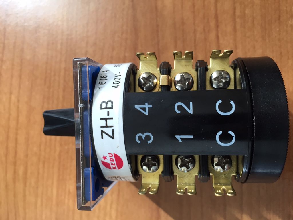
              One switch that would probably do the job is the reversing switch from a Seig C6 lathe. (early model) Arc Eurotrade sell these for £12.50 plus postage. (Arc's part number is C6-205 )The problem would be you would have to work out the contact arrangement on the switch. I think it would be too difficult to talk you through the steps required to do this and I live too far away from you to help. See how you get on with the resistance measurements. If you are lucky it could turn out to be a bad connection somewhere even though this is unlikely.

              Les.

              #186439
              kevin large
              Participant
                @kevinlarge76611

                Hi led

                A. L 20 N 2.5

                B. L 3.8. N 12.

                C. L 4.5. Ñ 125

                D. L NC. N. NC

                hope this helps again with the switch out I can get forward and reverse I do have to wiggle the lever for it to work sometimes

                I've looked at the switch you recommended I will contact them today to see if I can find out more about it

                Kevin

                #186445
                Les Jones 1
                Participant
                  @lesjones1

                  Hi Kevin,
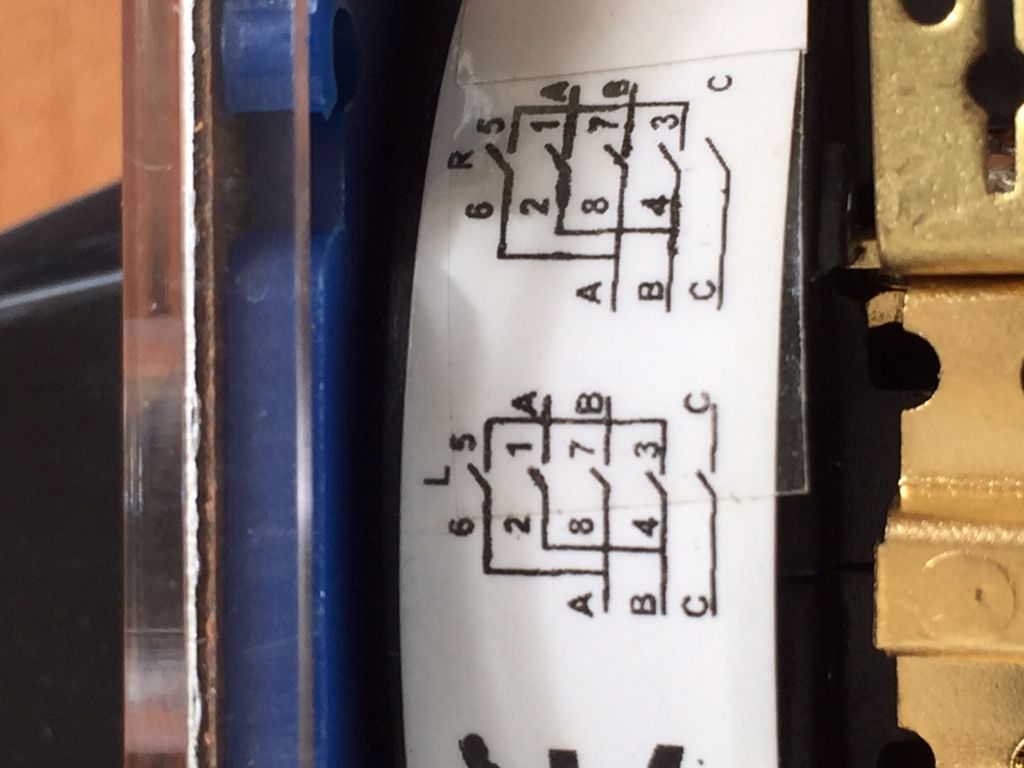
                  Your results confirm that the switch is faulty. The contact on the switch between terminals 7 & 8 is totally faulty. The resistance of the other contacts is a bit higher than I would expect. (I should have asked you to check the resistance of your meter test leads so that value could be subtracted from the readings.) Although Ketan and the others staff at Arc Euro Trade are extremely helpful I would not expect them to be be able to supply the information about the switch. If you were using it to replace the switch on A Seig C6 It would be just a matter of swapping the wires over from the old switch. I have managed to find some wiring diagrams for the C6 but non show the the labelling of the switch connections. They do show that the switch is functionally the same as your switch.

                  Les.

                  #186452
                  kevin large
                  Participant
                    @kevinlarge76611

                    Hi les
                    I took a look inside the switch it just fell apart lots of broken bits
                    I have telephoned about the the switch you said about and they confirmed what you said about diagram I will have a search and see if I can get 1 with diagram if not will try the 1 you said about
                    kevin

                    #186454
                    Steambuff
                    Participant
                      @steambuff

                      I know it is an outside chance but worth a try, have you phoned Warco to see if they have a spare?

                      Dave

                      #186462
                      Ketan Swali
                      Participant
                        @ketanswali79440

                        Kevin and Les,

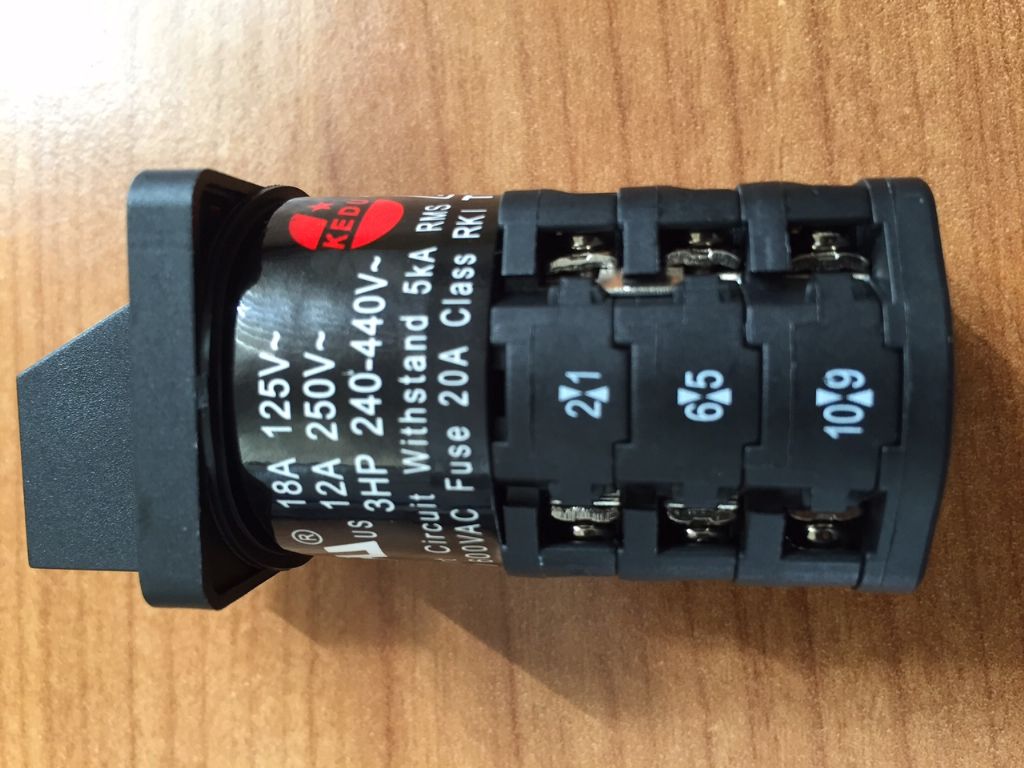
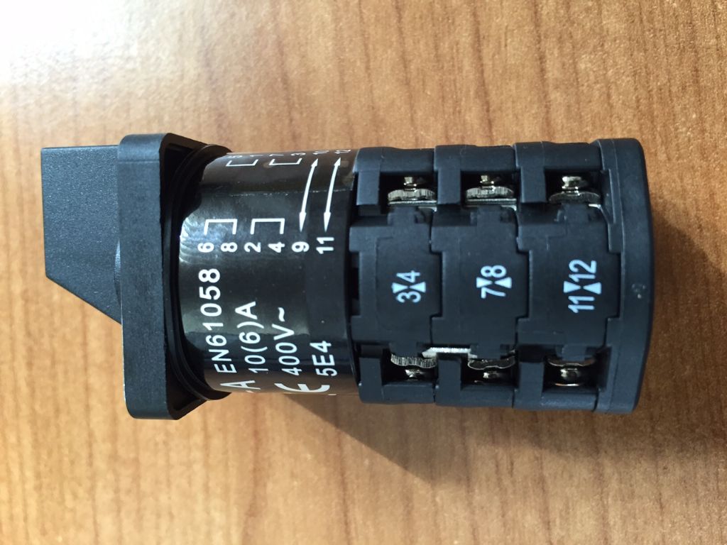
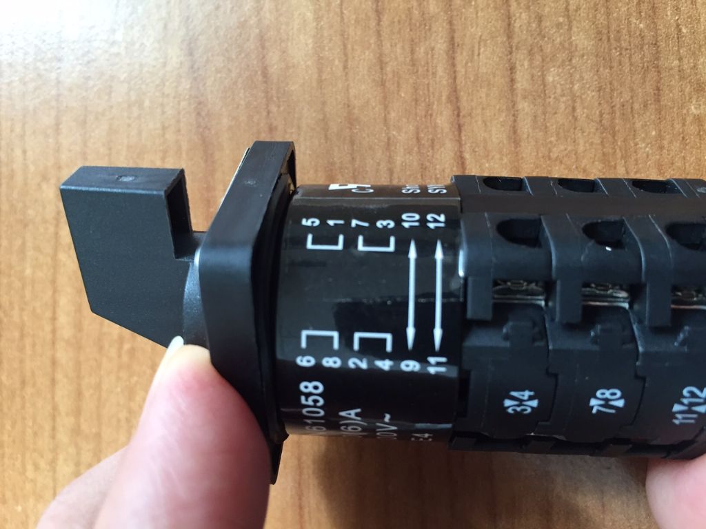
                        Came in a little late to this thread. Our Ian has informed me of his conversation with Kevin. Here are some close up pictures of parts C3-181 switch and C6-205. Don't know if they are of any help. They are also in the album, if you cannot see the details more clearly as part of this thread.

                        C3-181:

                        img_2055.jpg

                        img_2056.jpg

                        img_2057.jpg

                        C6-205:

                        img_2058.jpg

                        img_2059.jpg

                        img_2060.jpg

                        Ketan at ARC.

                        #186463
                        Les Jones 1
                        Participant
                          @lesjones1

                          Hi Ketan and Ian,
                          Thank you very much for going to the trouble of taking the pictures. Both switches would do the job but the last picture of the C-205 switch shows exactly how it works. This will save trying to talk Kevin checking the switch with his multimeter. (Kevin has very limited electrical knowledge.)
                          Once again an example of your superb customer service.

                          Many thanks again
                          Les.

                          #186465
                          Les Jones 1
                          Participant
                            @lesjones1

                            Hi Kevin,
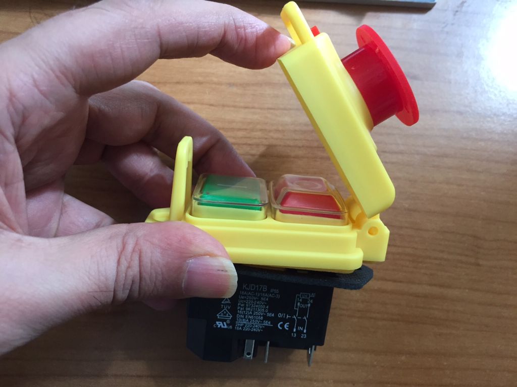
                            As you can see from my last post to Ketan the C6-205 switch will do the job without you having to do a lot of testing on the switch. The only functional difference to your existing switch is that it only breaks one pole to the main winding. This is not a problem. While you are making these changes it would be worth fitting an NVR switch.As well as a safety feature this will extend the life of the reversing switch as it would not be operated under load. It would also allow you to connect the interlock switches and emergency stop button. (With the right type of NVR.) I have found this one on ebay that would allow the use of the interlocks. I could not find any listed already mounted in a box that would allow the use of interlocks.

                            Les.

                            #186466
                            Nicholas Farr
                            Participant
                              @nicholasfarr14254

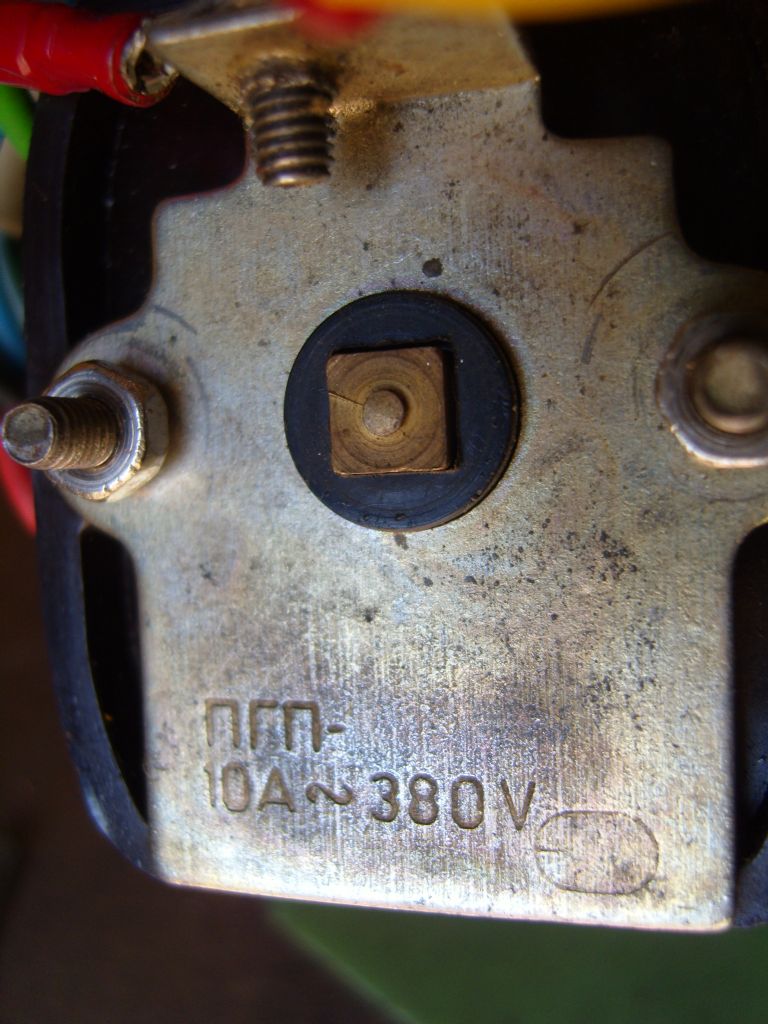
                              Hi Kevin and Les, I agree either of the switches that Katan has shown should be OK, as the original one is rated at 10A 380V these are easily capable of carrying the required load.

                              Switch Rating

                              Warco do an NVR containing an emergency stop button also, all contained in a box ready for mounting. **LINK**

                              Regards Nick.

                              Edited By Nicholas Farr on 15/04/2015 12:38:55

                              #186470
                              Bazyle
                              Participant
                                @bazyle

                                If you are left handed you might want a switch that is the other way round cool

                                Also helps for modern people who are too stupid to work out what the big red button is for.

                                #186474
                                Nicholas Farr
                                Participant
                                  @nicholasfarr14254
                                  Posted by Bazyle on 15/04/2015 12:46:20:

                                  If you are left handed you might want a switch that is the other way round cool

                                  Also helps for modern people who are too stupid to work out what the big red button is for.

                                  Hi, and almost £10.00 cheaper to boot.

                                  Regards Nick.

                                  #186476
                                  Ketan Swali
                                  Participant
                                    @ketanswali79440
                                    Posted by Les Jones 1 on 15/04/2015 12:20:39:

                                    Hi Kevin,
                                    As you can see from my last post to Ketan the C6-205 switch will do the job without you having to do a lot of testing on the switch. The only functional difference to your existing switch is that it only breaks one pole to the main winding. This is not a problem. While you are making these changes it would be worth fitting an NVR switch.As well as a safety feature this will extend the life of the reversing switch as it would not be operated under load. It would also allow you to connect the interlock switches and emergency stop button. (With the right type of NVR.) I have found this one on ebay that would allow the use of the interlocks. I could not find any listed already mounted in a box that would allow the use of interlocks.

                                    Les.

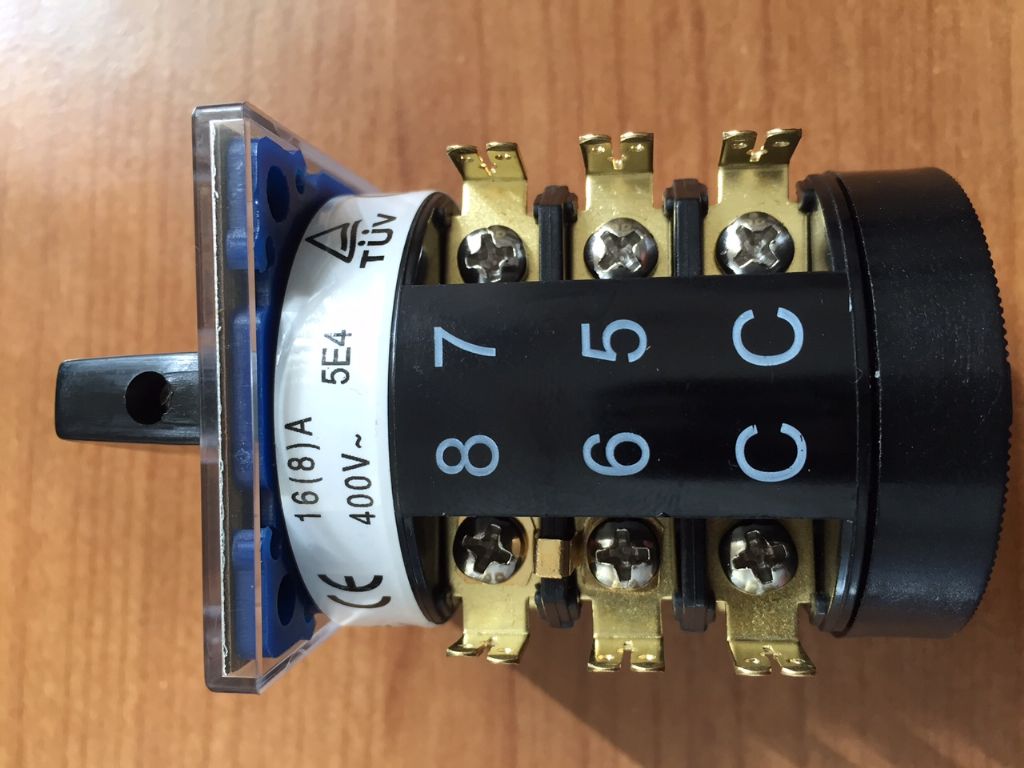
                                    Looking at your ebay link, it looks like a part which is in ARCs spares section: SC3-104:

                                    img_2061.jpg

                                    img_2062.jpg

                                    Ketan at ARC.

                                    #186482
                                    kevin large
                                    Participant
                                      @kevinlarge76611

                                      Thanks all switch and nvr ordered
                                      kevin

                                      #186489
                                      Les Jones 1
                                      Participant
                                        @lesjones1

                                        Hi Ketan,
                                        Yes it is the same. The important thing to allow the use of interlock switches is that one end of the coil is brought out to a terminal (A1) and not connected internally to the output terminal (23).

                                        Les.

                                        #186528
                                        Nicholas Farr
                                        Participant
                                          @nicholasfarr14254

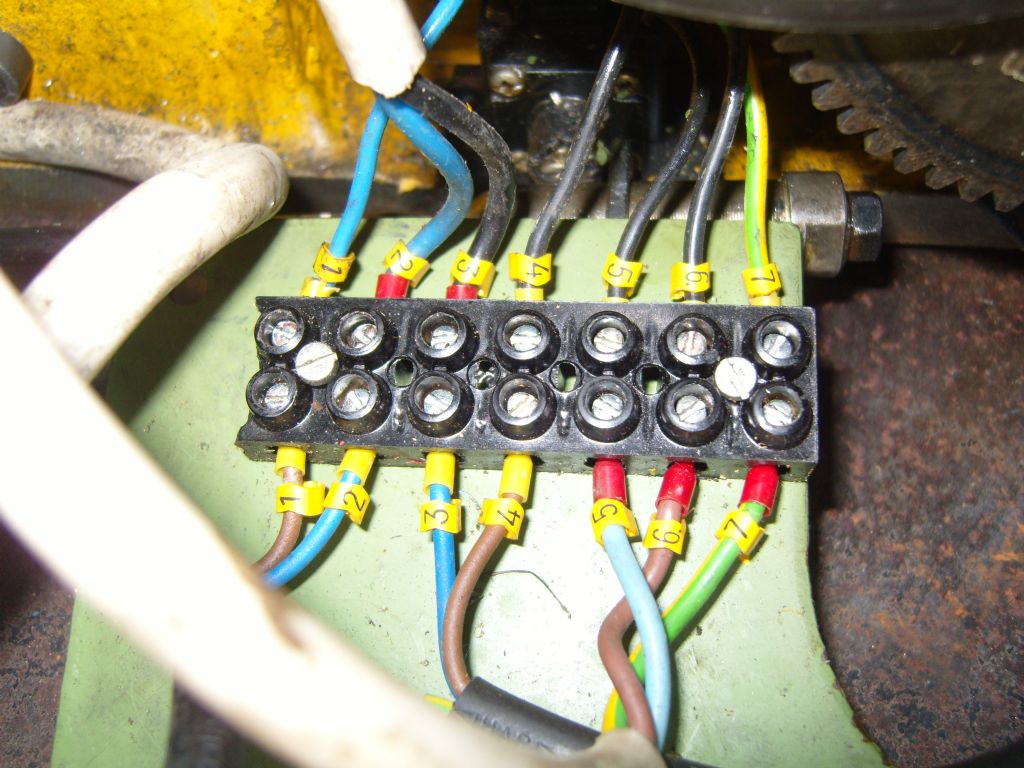
                                          Hi Les and Kevin, Les your mention of the interlock switches has prompted me in thinking that my original belief that the flex on Kevin's lathe that went into the original contactor box has been changed, because looking at his second photo down of his F/R switch and the connection block, there seems to be a lack of wires connected into it. It seemed to be a bit empty compared to mine but nothing has dawned on me before, my connection block has all the interlock wires connected into it and the flex coming from the contactor box is a five core one, containing three black wires, one blue and a green/yellow.

                                          Wiring Connection Block

                                          On the top row Nos. 1 and 4 are the interlock wires that trip the contactor, Nos. 2 and 3 are from the emergency stop at the tailstock end of the lathe bed, Nos. 5 and 6 are live and neutral from QF1 and 7 is earth.

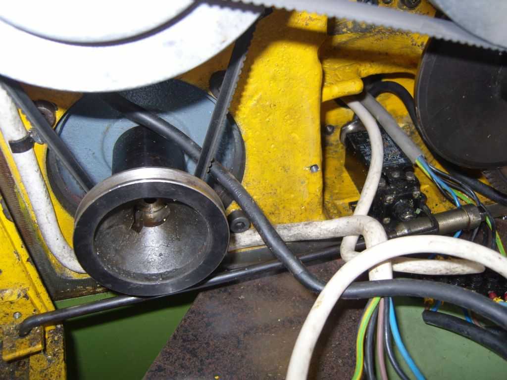
                                          On the bottom row Nos. 1 and 2 are the chuck guard switch, Nos. 3 and 4 are the gear/belt cover switch and Nos. 5, 6 and 7 go to the F/R switch. In the photo below can be seen the switch that is operated by opening the gear/belt cover acted by the rod that runs along the bottom and is anchored in the bracket of cover at the left hand side. The black flex behind the V belt goes up to the chuck guard switch,

                                          Gear Cover Interlock Switch

                                          I don't know if Kevin's emergency stop actually works, but if it does, it probably only cuts the live side and if it is reset without the F/R lever returned to the stop position, the lathe will restart straight away, which is very dangerous. I don't see any evidence of a chuck guard of gear/belt cover switch on Kevin's lathe, so interlocking will be very limited, might be a good idea if Kevin checks for any switches of any kind.

                                          Regards Nick.

                                          Edited By Nicholas Farr on 15/04/2015 18:39:53

                                          #186534
                                          kevin large
                                          Participant
                                            @kevinlarge76611

                                            Hi nick today I have ordered a new switch and the nvr
                                            my emergency stop button does work but I think that’s all it does I do have a chuck guard but there is no micro switches what are the interlock switches and where should they be but I’ve not seen any other electrical devices anywhere
                                            kevin

                                            #186538
                                            Nicholas Farr
                                            Participant
                                              @nicholasfarr14254

                                              Hi Kevin, the interlock switches stop the machine if you open the gear/belt cover or lift the chuck guard while it is running, they will also prevent the machine from starting if the gear/belt cover is open or if the chuck guard is not over the chuck in the correct place. You should have one just behind the top V belt pulley fixed to the frame near where the rod that the guard swings up and down on, you can see where the flex goes up to mine behind the V belt. You can see my gear/belt cover switch just below the flexes that come though from the other end of the lathe bed in my second photo in my last post. So if there is no kind of micro switch on the cover or at the end of the chuck guard rod inside the cover, they have probably been removed.

                                              Regards Nick.

                                              Edited By Nicholas Farr on 15/04/2015 19:15:28

                                              #186541
                                              kevin large
                                              Participant
                                                @kevinlarge76611

                                                Hi nick I defiantly don’t have these but I am sure I can manage without them as long as it won’t affect wiring in the new switch and various
                                                Kevin

                                                #186542
                                                kevin large
                                                Participant
                                                  @kevinlarge76611

                                                  I mean definitely

                                                  #186544
                                                  Nicholas Farr
                                                  Participant
                                                    @nicholasfarr14254

                                                    Hi Kevin, I would advise to get them fitted, if nothing else there ought to be one of some sort on the gear/belt guard.

                                                    Regards Nick.

                                                    #186663
                                                    kevin large
                                                    Participant
                                                      @kevinlarge76611

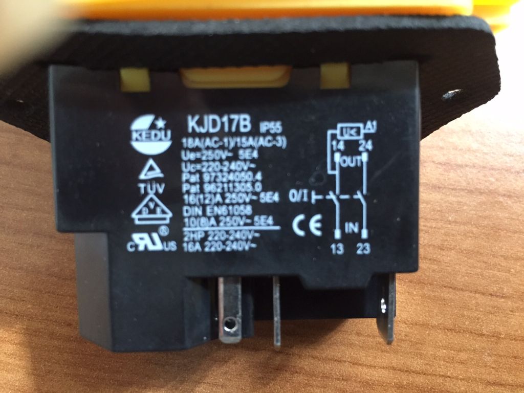
                                                      New switch arrived today fantastic service from arch if les or nick would be kind enough to tell me what wire goes where with a little diagram maybe good

                                                      The var is on the way I guess that just goes in in between the switch and the plug ?

                                                      Kevin

                                                      New switch

                                                    Viewing 25 posts - 51 through 75 (of 96 total)
                                                    • Please log in to reply to this topic. Registering is free and easy using the links on the menu at the top of this page.

                                                    Advert

                                                    Latest Replies

                                                    Home Forums General Questions Topics

                                                    Viewing 25 topics - 1 through 25 (of 25 total)
                                                    Viewing 25 topics - 1 through 25 (of 25 total)

                                                    View full reply list.

                                                    Advert

                                                    Newsletter Sign-up