Division Master (Stepper Motor Dividing)

Advert

Division Master (Stepper Motor Dividing)

Home Forums Workshop Tools and Tooling Division Master (Stepper Motor Dividing)

Viewing 19 posts - 26 through 44 (of 44 total)
  • Author
    Posts
  • #333857
    Carl Wilson 4
    Participant
      @carlwilson4

      Hi John,

      Merry Christmas. I hope you find the stepper driven rotary table as useful as I have.

      Mine was an eight wire motor. I wired the coils in series as Dave mentions to end up with a four wire motor.

      Zapp give data sheets for all their motors giving wire colours and a diagram of the coils so you can see what’s what.

      Advert
      #333874
      Douglas Johnston
      Participant
        @douglasjohnston98463

        Is there a connection between all the double posts and the quantity of Christmas spirit about?

        Doug

        #333877
        john fletcher 1
        Participant
          @johnfletcher1

          Ah, one minor problem solved, so a four wire motor will be OK. Got the housing done, using what I had under the bench and other bits are on the way. Several club members are also making the rotary table driver, pooling our brains sort of thing. Happy Christmas to all and don't go away as I / we, maybe looking for a life line again in 2018. John

          #333880
          Carl Wilson 4
          Participant
            @carlwilson4

            Christmas spirit not to blame just tiredness. I’m working on a ship. My Xmas day is machining some threaded bushes on a big Chinese lathe.

            If you need any help with this project or your club mates do please pm me or email me.

            You can look at my blog too, British Reaction Research. There is a build log for the unit. It’s in 2015’s posts.

            Merry Christmas,

            Carl.

            #333889
            Robin
            Participant
              @robin

              I designed the perfect stepper mount. You bolt the motor shaft to the end of the shaft you want to turn. You run a bar out sideways from the motor body. The bar comes up against a stop. You add a spring to pull the bar against the stop and there you have it. It is mechanically perfect, stress free, cheap as chips, no possibility of backlash, any misalignment is self cancelling. Unfortunately it would look ghastly and the motor is going to wobble all over the place. Can't bring myself to do it dont know

              #395152
              Mark Simpson 1
              Participant
                @marksimpson1

                Hi

                I've a 15" rotary table 90:1 to which I need to add a means of dividing for 55,66, and 76 (for spur gear cutting)
                it currently has no dividing gear so I have to build something…..

                I've also a 6" elliott dividing head with one plate, which I've successfully used to cut a couple of smaller spur gears.

                Reading this thread and others it seems most sense to build a stepper motor dividing system than I can switch between both…. I guess Steve (world of ward) wards controller, or the Arduino one Like Carl Wilson in issue 249 would now be the logical place to start; no problem with either (I think)

                The resource I cannot find is about Stepper Motor Specification..My 15" table is a lot bigger than a 6" vertex, especially with a 19.5" gear on it. Is a Nema 23 1.8Nm stepper enough? Should I gear it down with T?? pulleys/belt(might also make get the drive to a better location

                Any suggestions/tips really welcome

                Thanks Mark

                #395164
                Anonymous

                  Personally I wouldn't faff around with stepper motors and electronics. One simple solution is to make a riser block for the dividing head. If that means the bigger gears won't go under the arbor (assuming you're using a horizontal) then I'd just create a spreadsheet and use that to set the rotary table for each angle. Not difficult, providing you take account of any backlash.

                  Andrew

                  #395165
                  SillyOldDuffer
                  Moderator
                    @sillyoldduffer
                    Posted by Mark Simpson 1 on 07/02/2019 11:41:16:

                    Hi

                    I've a 15" rotary table 90:1 to which I need to add a means of dividing for 55,66, and 76 (for spur gear cutting)
                    it currently has no dividing gear so I have to build something…..

                    I've also a 6" elliott dividing head with one plate, which I've successfully used to cut a couple of smaller spur gears.

                    Reading this thread and others it seems most sense to build a stepper motor dividing system than I can switch between both…. I guess Steve (world of ward) wards controller, or the Arduino one Like Carl Wilson in issue 249 would now be the logical place to start; no problem with either (I think)

                    The resource I cannot find is about Stepper Motor Specification..My 15" table is a lot bigger than a 6" vertex, especially with a 19.5" gear on it. Is a Nema 23 1.8Nm stepper enough? Should I gear it down with T?? pulleys/belt(might also make get the drive to a better location

                    Any suggestions/tips really welcome

                    Thanks Mark

                    How difficult is your 15" table to turn compared with the 6"? Unless the 15" is much stiffer (perhaps when heavily loaded), I'd expect a 1.8Nm to turn it well enough. The motor only has to provide as much torque to the table drive as a human does when turning the hand-wheel, probably not much. If the table is very stiff you could measure the torque needed to turn it and buy a motor to suit. (Ask again if you need to measure torque.)

                    Carl's divider as described in his MEW article uses an Arduino and software developed by Gary Limings. The display and keyboard are a standard module. Provided you have a computer it's easy (and free) to install Gary's program on the Arduino and the electronics are a straightforward wiring job. A limitation of the keyboard module is that it only provides 5 buttons, making it necessary for the operator to navigate a nested menu structure, which some find annoying or hard to remember.

                    Steve Ward's divider uses a 4×4 keypad and a PIC controller. Full build and user instructions on the web. It doesn't need the nested menus that make the Liming's software a little clunky to use. However, installing programs on a PIC is rather more complicated than the same job on an Arduino and the electronics are also more work, though I believe they are available as a kit. PIC is not outrageously more complicated than Arduino but the Arduino family – hardware and software – benefit from several features designed to make them beginner-friendly.

                    Banging my own drum, following a challenge from the late great John Stevenson who disliked nested menus, my effort uses an Arduino, an I2C LCD display (standard item), and a 4×4 keypad. No nested menus, and – like Steve Ward's divider – more natural operation. It is not a clone. Main problem is that the documentation is unpolished – I was going to write it up as an article but felt it was too soon after Gary's to have any appeal. An undeveloped feature that might be useful is that the divider can be controlled by a remote computer over a serial interface; the client software would have to be written by the user. In stand-alone mode everything works and it's been built by at least two others apart from me. Details here if anyone is interested, the latest version is in the folder 'keypad_i2c'

                    Dave

                    #395169
                    JasonB
                    Moderator
                      @jasonb

                      Could also knock up a plate with the required number of holes in it using a DRO and then disengage the worm and direct index the gears.

                      #395187
                      Martin Connelly
                      Participant
                        @martinconnelly55370

                        This thread **LINK** mentions the required accuracy of dividing plates so may be of interest.

                        Martin C

                        #395202
                        Mark Simpson 1
                        Participant
                          @marksimpson1

                          Thanks to All:

                          Andrew: it's a KRV3000 (Bridgeport on steroids) with a homemade horizontal attachment. Max clearance between Arbour and table about 11". The 3 bigger gears for my 6" Little Samson are 14.25", 17.00" and 19.5" so a switch to horizontal and use the rotary table and cur in Z axis seems the only choice. Spreadsheet doable but some risk (to my mind) at 4.737 deg / tooth

                          Dave: thanks for the advice on ways to generate the steps, I have used aruino before and no problem with coding for it. I had also watched your discussion with the great JS and appreciate the input… It takes more to move the big RT handle, but not so much more torque than the small RT.

                          Jason: I had not thought of that… If I knock up a plate say 12" diameter with my DRO I should be able to get the holes accurate to maybe .001"(maybe .002&quot if I am careful. Those errors would (I guess) tend to magnify up to the outer diameter where the teeth are (so perhaps .003" at 19.5" diameter)… It's a traction engine so not high speed, no idea if .003" possible deviation on tooth width is acceptable
                          Many Thanks for the ideas
                          Mark

                          #395225
                          John Olsen
                          Participant
                            @johnolsen79199

                            Mark, if you make up a division plate by any convenient means and then use it to divide with, the angular errors will be divided by the ratio of the worm in the dividing head or rotary table. For instance if the worm ratio is 60 to 1, and you get one hole out by one degree on a home made division plate, then the error on the actual gear will be 1/60 degree, or one minute. So this means that if you make a plate by say using the hole layout function on a DRO, and then use the plate with a dividing head, the error will be negligible.

                            Because of this you can do things like print out a template from CAD on a laser printer and then spot through the holes to make a plate, or even just mark out a plate by hand. Or use the rotary table with a spreadsheet list.

                            Actually anything you do is likely to be much more accurate than the originals. I think most traction engine gears were just cast and then used as is.

                            John

                            #395358
                            Anonymous
                              Posted by Mark Simpson 1 on 07/02/2019 17:16:15:

                              Andrew: it's a KRV3000 (Bridgeport on steroids) with a homemade horizontal attachment. Max clearance between Arbour and table about 11". The 3 bigger gears for my 6" Little Samson are 14.25", 17.00" and 19.5" so a switch to horizontal and use the rotary table and cur in Z axis seems the only choice. Spreadsheet doable but some risk (to my mind) at 4.737 deg / tooth

                              Yep, been there, done that!

                              final drive gear cutting.jpg

                              These final drive gears have 72 teeth, so each increment is a handy 5 degrees, although I still needed a spreadsheet as one rotation of the handle is 4 degrees.

                              As John says errors are reduced by the ratio of the worm. One complete turn of the handle (360 degrees) only turns the table 4 degrees. Let's look at the maths. My gears are 72 teeth and 5DP do the PCD is 14.4", giving a circumference of 45.239". Consider a position error of 5 thou on the circumference. There are about 9047.8 5 thou arcs on the circumference. Each 5 thou arc represents an angle of 0.0398 degrees. On the handwheel that is represented by an error of 3.58 degrees (multiply by 90). I would think that is doable. But 0.0398 degrees is about 2.38 minutes of arc. I doubt my no name rotary table accuracy is much better than that anyway.

                              There is at least 5 thou backlash on my final drive gears, but I suspect that is more related to slight over cutting of the tooth depth. When I got back to the original cut the cutter went through with barely a sound, as one would expect.

                              Andrew

                              #395361
                              Emgee
                              Participant
                                @emgee

                                Andrew, does the mill have a powered knee or did you have to crank all of those cuts ?

                                Emgee

                                #395398
                                Anonymous
                                  Posted by Emgee on 08/02/2019 22:25:12:

                                  Andrew, does the mill have a powered knee or did you have to crank all of those cuts ?

                                  Nope, all done by hand. I actually cut six gears, four for my two engines and a mate who is building the same engine just 'happened' to have his two blanks ready at the same time. That makes 432 teeth; 12 turns down and 12 turns up for each tooth. That's a lot of handle w**king. I could do about half a gear at a time before needing tea and biscuits.

                                  Andrew

                                  #395410
                                  Andy Carruthers
                                  Participant
                                    @andycarruthers33275

                                    Counts as exercise in my book, and lovely job well done too

                                    #395767
                                    Mark Simpson 1
                                    Participant
                                      @marksimpson1

                                      Andrew: Thank you, it's really good to know that someone with more experience has cut these large gears in the same way as I intend to… Horizontal RT, lock X and Y, and wind the table up and down… (good exercise!)

                                      Also good to know that 5 thou backlash is a reasonable figure for TE gearing, I am less worried about the absolute accuracy of the thing now, but still want to do a good job.

                                      On the division front I think I will have to do something more than "wind the handle to a spreadsheet"

                                      • My divisions are all awkward numbers as degrees… (76 teeth=4.737deg, 66 teeth=4.535deg, 55 = 6.455 deg
                                      • I work full time so I am unlikely to manage all the teeth on any gear at one sitting
                                      • I make mistakes and 55+66+76 is a lot of opportunity for Captain Cockup to pay a visit.

                                      I do use my rotary table instead of a bigger lathe, so some way to drive the rotary table continuously would have additional benefits….

                                      I've priced the stepper motor route at about £100 ( I have a suitable power supply already) and will have a go that way, building a whole division mechanism for the RT to cut 3 gears seems like too much effort

                                      I do still like Jason's Idea to produce a large division plate and bolt it to the top of the gears then release the worm on the RT…. Easy, Cheap and I can check the accuracy of the division plate before cutting any teeth by measuring between the holes… I love a practical solution!

                                      Many Thanks
                                      Mark

                                      #395774
                                      Anonymous
                                        Posted by Mark Simpson 1 on 11/02/2019 10:18:03:

                                        Also good to know that 5 thou backlash is a reasonable figure for TE gearing, I am less worried about the absolute accuracy of the thing now, but still want to do a good job.

                                        These are not precision gears. As has been stated, in fullsize the final drive gears would have been as cast, with any lumps tidied up with a hammer and cold chisel.

                                        Andrew

                                        #400327
                                        Mark Simpson 1
                                        Participant
                                          @marksimpson1

                                          Quick progress update…

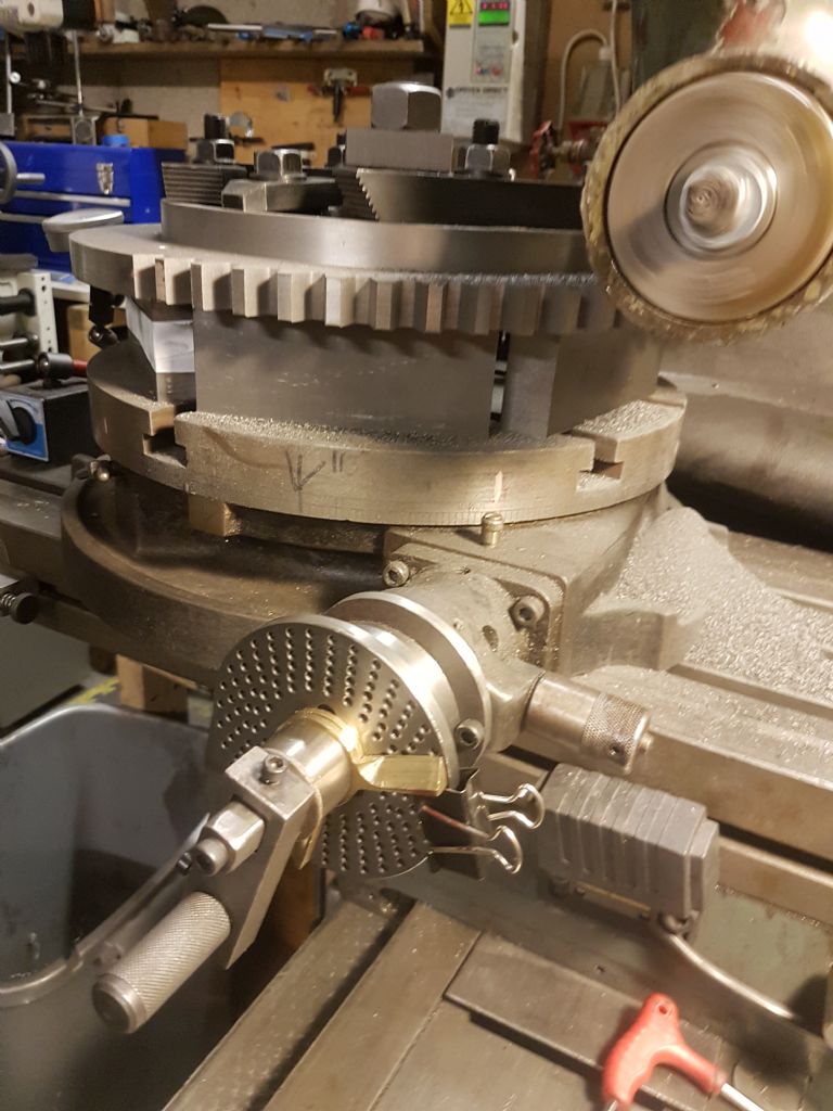
                                          I found that the dividing plates from a 6" table had a big enough bore (22mm), so made a mounting for them on my 14" table, made a new handle for it and it seems to work fine. Stepper motor route would perhaps have been better in the long run but I already had the plates for the 6" and decided to go for it (and not spend 100+quid)

                                          20190314_085148.jpg

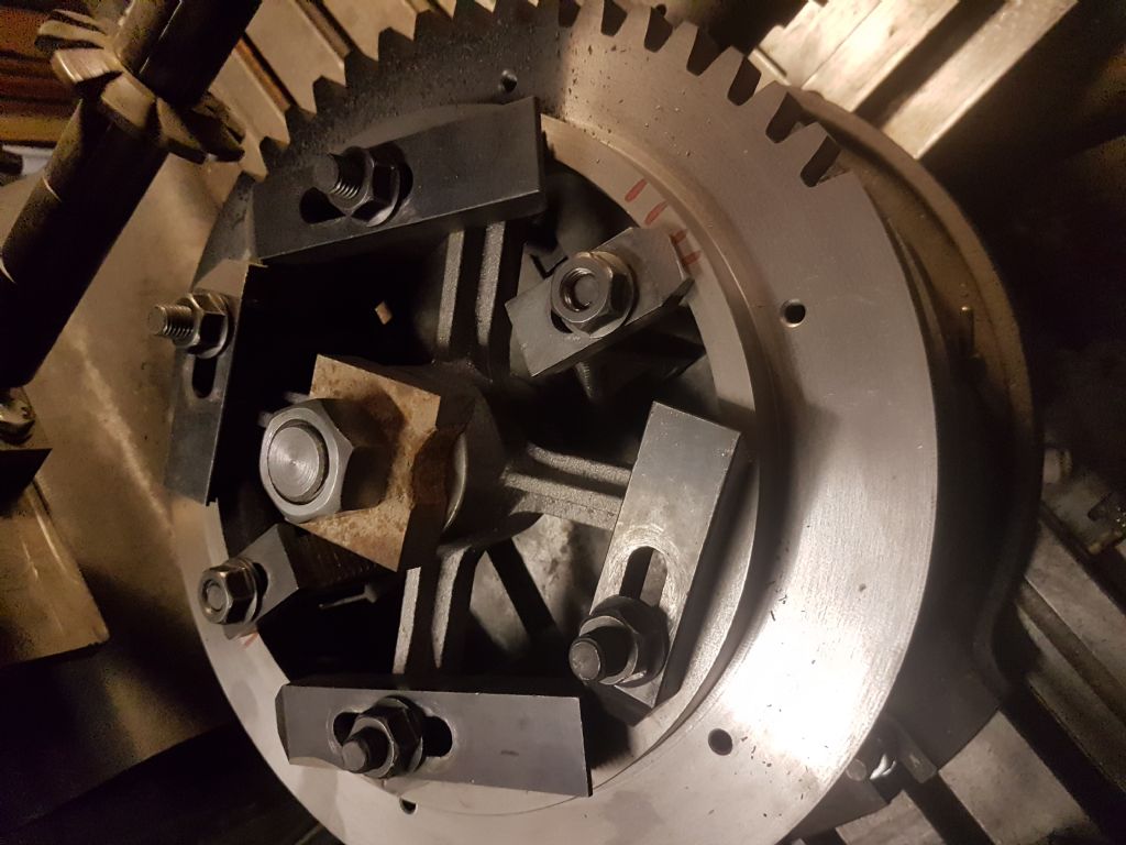
                                          Then had to lift the gear blank off the table, and after investigating the price of 4 off 2" tall parallels I bought 3' of 2"x1" mild steel bar and added 5 thou of shim in 2 places (it's a one off setup after all). Added 6 clamps and a 1" whit stud and started cutting teeth
                                          20190314_085158.jpg

                                          It seems a very solid setup, and have been able to cut the 4DP, .539" deep teeth in one go

                                          as Andrew mentioned, it's a lot of handle winding, but very satisfying

                                          Thanks again for the advice, all useful

                                        Viewing 19 posts - 26 through 44 (of 44 total)
                                        • Please log in to reply to this topic. Registering is free and easy using the links on the menu at the top of this page.

                                        Advert

                                        Latest Replies

                                        Viewing 25 topics - 1 through 25 (of 25 total)
                                        Viewing 25 topics - 1 through 25 (of 25 total)

                                        View full reply list.

                                        Advert

                                        Newsletter Sign-up