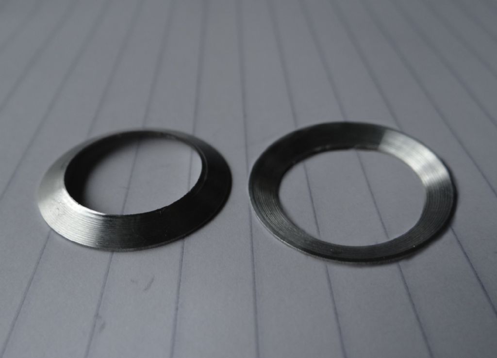
Pitched aluminium rings. Any ideas how to machine them?

Advert

Pitched aluminium rings. Any ideas how to machine them?

Home Forums Beginners questions Pitched aluminium rings. Any ideas how to machine them?

Viewing 25 posts - 1 through 25 (of 27 total)
  • Author
    Posts
  • #394534
    Christopher Buxton
    Participant
      @christopherbuxton96596

      Hi there, so I’m a newbie to the engineering world and probably trying to jump in at the deep end.
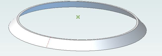
      I want to reproduce some watch bezel inserts from aluminium.If they were flat then probably not too difficult to make on the lathe but unfortunately they are conical.I can get some stock aluminium tube that’s less than a mm too big O.d and I.d so very little machining there. If I get the correct pitch from the leading face using the lathe then I can cut off. That just leaves the back to do. Would I need a milling machine to do this or could I cut off at an angle?
      Dimensions are 37.7mm o.d 0.4mm depth 31.7mm I.d 0.7 mm depth. Think the pitch is 27 degree putting the dimensions into a trapezoid calculator. I’ve put photos into an album but not sure how to add them to this post. Thanks for advice

      Advert
      #9513
      Christopher Buxton
      Participant
        @christopherbuxton96596
        #394542
        Howard Lewis
        Participant
          @howardlewis46836

          Could you turn the chamfer on the outer end, (offset Top Slide) and then carefully part off?

          Or maybe I've misunderstood the shape.

          Howard

          #394543
          Emgee
          Participant
            @emgee

            Hi Christopher

            Welcome to the Forum, you could turn the internal angle (bevel) on a lathe by setting the top slide over to the required angle.
            The external angle may be possible by turning the bevel before parting, or even parting off at the required angle, this would be quite difficult to do, especially if there was no flat area at the ID of the part.

            You may be able to turn a flat ring and make a simple press tool and former to achieve the bevel shape.

            Emgee

            #394545
            Christopher Buxton
            Participant
              @christopherbuxton96596

              Hi Howard,
              Thanks for your reply. Are you able to view photos in my album?

              #394549
              JasonB
              Moderator
                @jasonb

                conical.jpg

                From the top

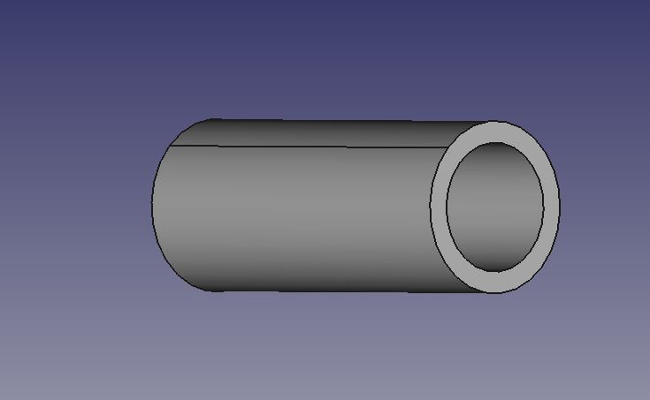
                1. face the end of your tube

                2. Reduce OD and bore ID to finish size

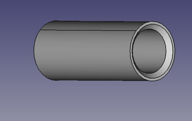
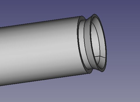
                3 Set over topslide to cut tapered underside

                4 Parting cut most of the way through to height

                5 With topslide still set at same angle machine the top slope

                6 Complete parting cut to separate part

                conical2.jpg

                Edited By JasonB on 03/02/2019 19:32:48

                #394550
                Michael Gilligan
                Participant
                  @michaelgilligan61133

                  The design and manufacture of suitable chucks for this sort of work is featured in the current issue 277 of MEW.

                  **LINK**

                  https://www.model-engineer.co.uk/editorial/page.asp?p=250

                  Well worth a look.

                  MichaelG.

                  .

                  Edit: … am I right in thinking that there are 'beaded edges' visible on the underside ?

                  https://www.model-engineer.co.uk/wp-content/uploads/sites/4/images/member_albums/179580/823476.jpg

                  Edited By Michael Gilligan on 03/02/2019 19:44:02

                  #394555
                  SillyOldDuffer
                  Moderator
                    @sillyoldduffer

                    Similar to Jason:

                    Step 1, face off and bore tube to the diameter of the bevel's inner ring at the narrow end.

                    step1.jpg

                    Step 2, offset the tool-post and chamfer the inside.

                    step2.jpg

                    Step 3, cut the outer chamfer

                    step3.jpg

                    Then part off. If necessary for a better finish I'd superglue the clean end of the bevel to a rod held in the chuck and skim the parted-off side with a sharp tool.

                    From the comfort of my armchair, not difficult to do by angling the tool-post. Apart from the extreme delicacy needed while cutting that is! As Emgee mentions, manufactured bevels could well be made by stamping rather than turning.

                    Please report back, it's a challenge!

                    Dave

                    Edited By SillyOldDuffer on 03/02/2019 20:17:40

                    #394561
                    Emgee
                    Participant
                      @emgee

                      After further consideration I believe myself, Jason and Dave are expecting a lot of a newcomer without a lot of experience using a lathe to be able to do such delicate work, especially if he uses the tube mentioned in the post, I now feel stamping seems to be his best bet.

                      Emgee.

                      Edited By Emgee on 03/02/2019 21:43:28

                      #394638
                      Christopher Buxton
                      Participant
                        @christopherbuxton96596

                        Thanks for the awesome illustrations.I now know how to tackle it. I only have a boley watchmakers lathe with compound cross-slide but hopefully as it’s a soft metal it might do the job. I don’t want to make any big purchases on a larger lathe or milling machine right now until I know whether I can complete the next steps successfully. I.e black anodizing then printing the silver markers and numbers, either by pad printing, laser etching or chemical etching. So just a few blanks hand turned should be sufficient. Then I might look at making or buying a press as Emgee suggested to get a small production line going. Anything on a larger scale I think a laser cutting service would be needed. As soon as I get the materials I need I will document and post the results.

                        #394688
                        SillyOldDuffer
                        Moderator
                          @sillyoldduffer

                          Emgee's concern this might be too delicate got me out of my armchair following my own advice.

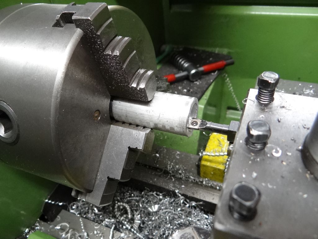
                          First I bored an 18mm cavity into a bit of scrap Aluminium 22mm diameter rod. (Although scrap the alloy is known to machine well.)

                          boring.jpg

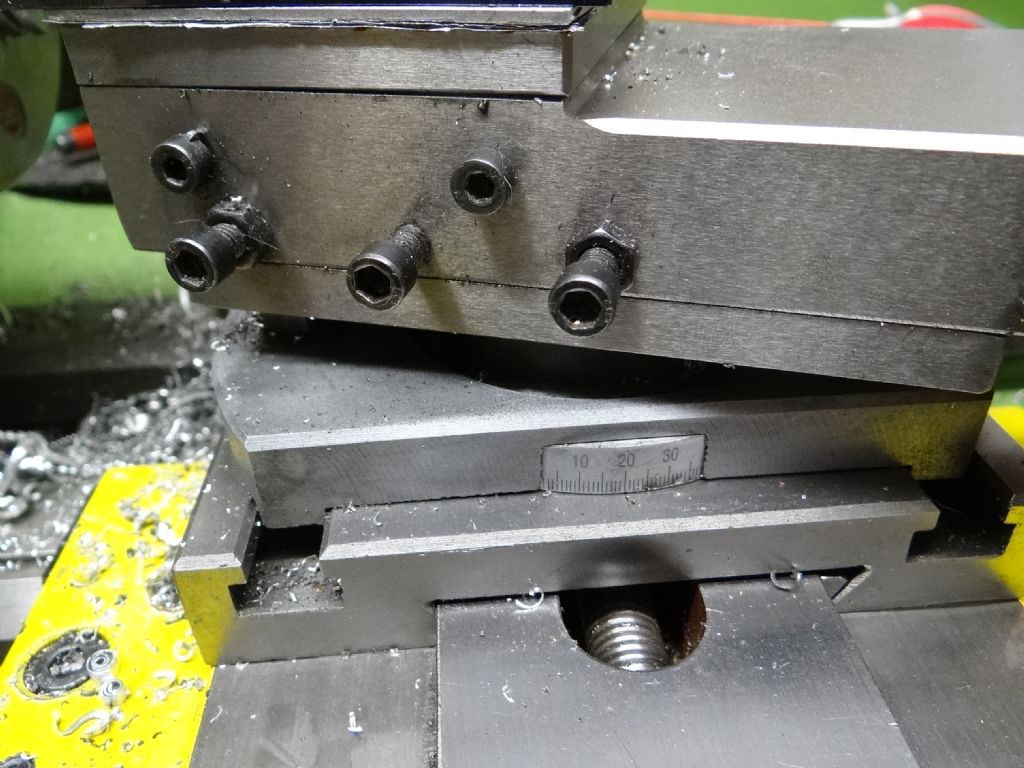
                          Then I angled the tool-post:

                          angletoolpost.jpg

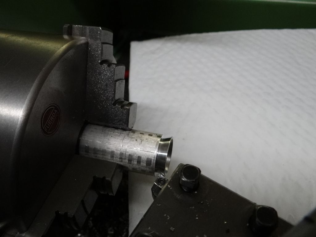
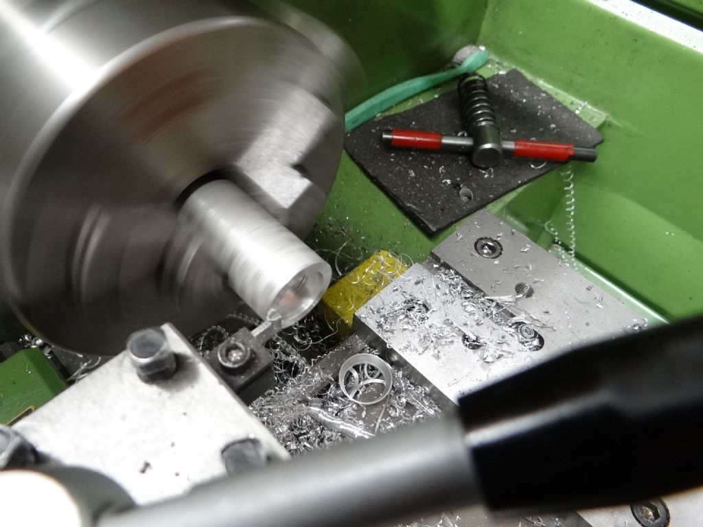
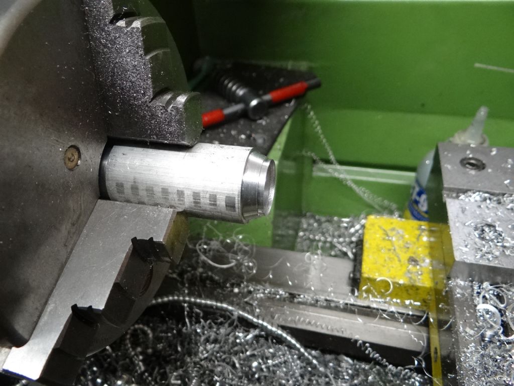
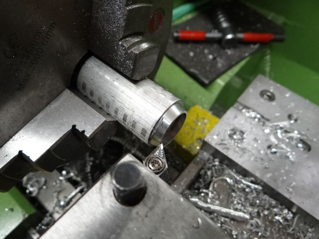
                          and widened the hole by cutting a 20 degree bevel into it. The tool was traversed by the topslide and was happy taking 0.8mm cuts. Main problem was chatter on the shallow finishing cuts, but note I used an ordinary coated blunt insert rather than a sharp one intended for non-ferrous metals.

                          innerchamfer.jpg

                          innerdone.jpg

                          Without altering the angle of the toolpost I switched to a left-hand insert, which happened to be correct for Aluminium and cut the outer chamfer. I narrowed the wall down to 0.6mm (messed up – it's actually 0.52mm)

                          outerchamfer.jpg

                          Then reset the toolpost to 0 degrees and parted off:

                          partedoff.jpg

                          As it didn't part-off cleanly:

                          needstidy.jpg

                          I superglued the ring backwards on to the rod

                          gluedback.jpg

                          Then switched to a sharp right-hand tool and tidied up:

                          refaced.jpg

                          In the past I've easily broken Poundshop superglue joints by leaving them in boiling water for a few minutes. Not so this time with proper Locktite – it has better heat resistance and I had to blowlamp it for a few seconds.

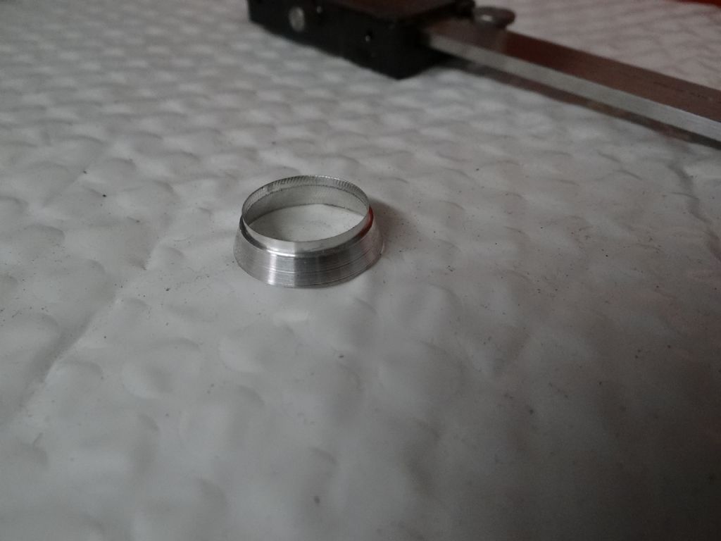
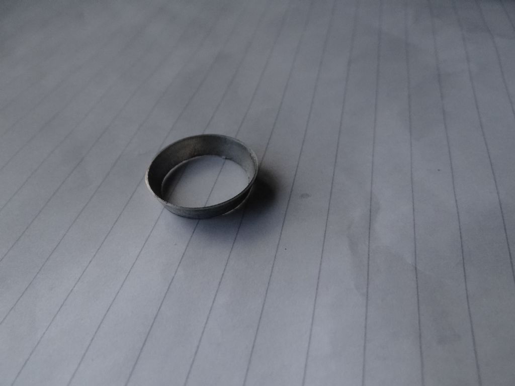
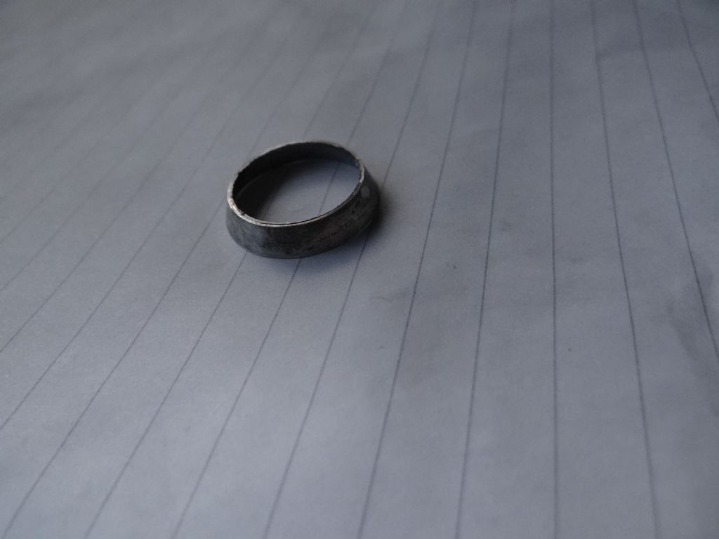
                          finishedback.jpg

                          finishedf.jpg

                          Wasn't difficult to do and I could have got a much better finish with a little more work. Despite my legendary clumsiness and use of carbide rather than sharp HSS the bevel wasn't stressed during cutting. I'd bet money on Christopher succeeding – if I can do it anyone can.

                          Only issue was making sure tools cutting at an angle didn't foul the work. Also, switching to a right-hand knife rather than using a boring bar to make the inner chamfer would probably have eliminated the chatter.

                          Dave

                          #394695
                          Michael Gilligan
                          Participant
                            @michaelgilligan61133

                            Nice demonstration, Dave

                            … 'though the angle looks somewhat different to the example in Christopher's album.

                            I suspect that his version may prove trickier.

                            MichaelG.

                            .

                            [heckling from the safe haven of my armchair] blush

                            #394701
                            JasonB
                            Moderator
                              @jasonb

                              In true Blue Peter Style here is one I prepared earlier (about 10 years ago) 1.125" OD, 30deg slope which is not far off the OP's 27deg, 0.025" thickness, Steel. Finish looks bad at this magnification!

                              20190204_172147[1].jpg

                              20190204_172229[1].jpg

                              20190204_172304[1].jpg

                              Just done on the end of a bit of bar in the 3 jaw, more or less the same as I suggested above.

                              Edited By JasonB on 04/02/2019 18:28:01

                              #394705
                              Martin W
                              Participant
                                @martinw

                                Hi

                                Just printed out one of the photos showing the bezel ring edge on and measured the angle of the bezel to the base and this gives an included angle of 22.5 deg. Before anyone jumps up and down I know that this is not the way determine the 'true' angle on the bezel. I think that SOD by offsetting the top slide by 20 deg actually cut an included angle of 70 deg rather than 27 deg and this would account for SOD's bezel looking very different from the pictures. That said Dave clearly illustrates one method of producing the particular part on a lathe which is what Christopher wanted which was the point.

                                Cheers

                                Martin W

                                #394709
                                Michael Gilligan
                                Participant
                                  @michaelgilligan61133
                                  Posted by Martin W on 04/02/2019 18:46:54:

                                  I think that SOD by offsetting the top slide by 20 deg actually cut an included angle of 70 deg rather than 27 deg and this would account for SOD's bezel looking very different from the pictures.

                                  .

                                  Yes, that was my point, Martin

                                  … Jason's is much flatter.

                                  MichaelG.

                                  Edited By Michael Gilligan on 04/02/2019 18:52:02

                                  #394729
                                  duncan webster 1
                                  Participant
                                    @duncanwebster1

                                    +1 for SOD method, but I'd have machined a groove with a parting tool so that the outer chamfer ran into fresh air rather than becoming a wider and wider cut.

                                    #394771
                                    Tim Stevens
                                    Participant
                                      @timstevens64731

                                      Jason – if your three pictures above were done with the same settings, they are a very good example of the colour bias created by cameras which try to achieve an overall 'standard' colour balance. The same effect causes tools which are just less than new to look really rusty, unless there is plenty of red in the background.

                                      Perhaps this effect has caused others problems, so I hope this helps someone.

                                      cheers, Tim

                                      #394772
                                      Hopper
                                      Participant
                                        @hopper

                                        Yes, "automatic" camera settings can be a bit like "universal" motorcycle parts: they almost fit everything but don't quite fit anything.

                                        #394794
                                        Michael Gilligan
                                        Participant
                                          @michaelgilligan61133
                                          Posted by Tim Stevens on 05/02/2019 11:05:57:

                                          Jason – if your three pictures above were done with the same settings …

                                          .

                                          As we know : Everything lump of metal that Jason machines 'turns to gold'

                                          MichaelG.

                                          angel

                                          #394798
                                          SillyOldDuffer
                                          Moderator
                                            @sillyoldduffer

                                            Forgive me if this is getting boring but I think there's a little more beginner interest to be squeezed from the question.

                                            In my defence I deliberately cut a 70° bevel rather than the shallow 27° mentioned by Chris because I thought it would be easier to photograph. I ignored Chris's other dimensions as well – they didn't match the scrap in my junk box!

                                            But people noticing the angle was 'wrong' allows me to comment on angling the tool-post as a problem.

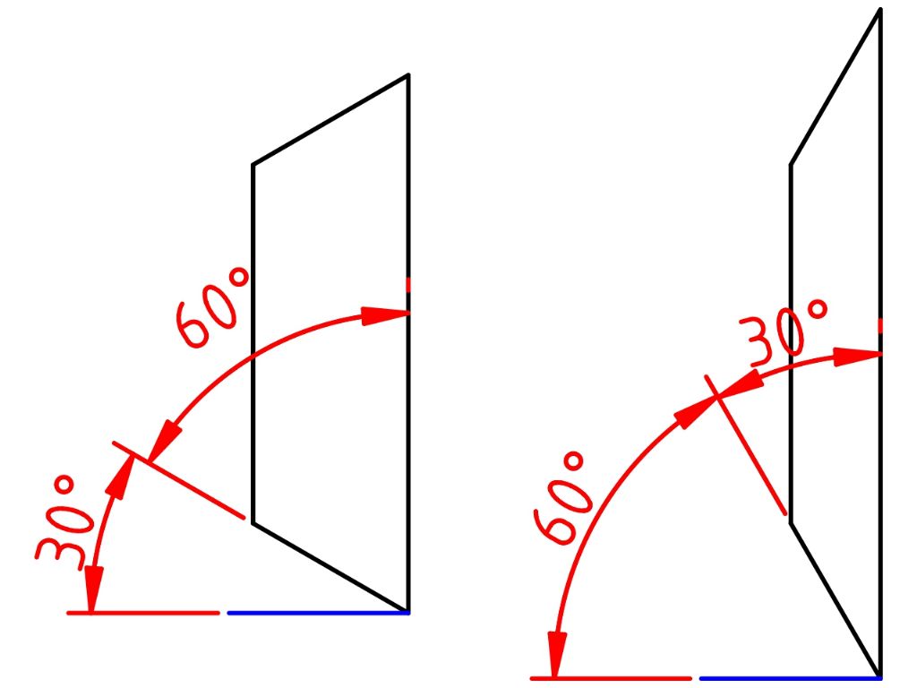
                                            Not all lathes have an angle scale fitted. These have to be set either by gauge or by calculation, which might be necessary for accuracy anyway. On lathes fitted with with an angle scale the maker has a choice between showing either the post's angle to the saddle, or its complement ( 'opposite' ) which is the angle the tool cuts relative to the spindle axis. Getting it wrong makes a difference!

                                            compangles.jpg


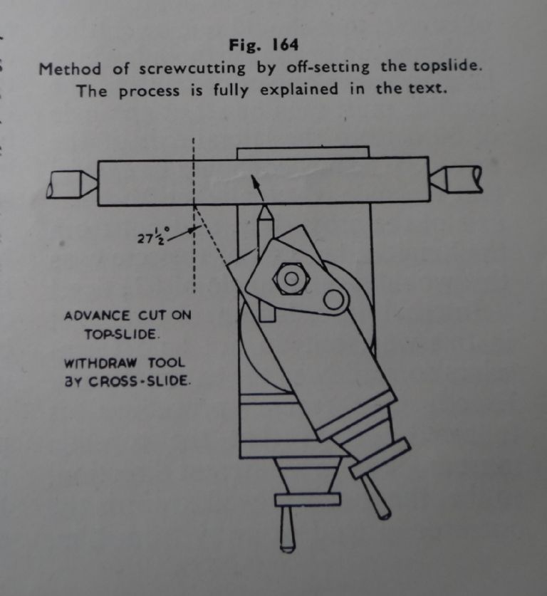
                                            Quite a lot of beginners, including me, get caught when first attempting a screw-thread using the recommended set-over top-slide method as per the excellent Mr Sparey.

                                            dsc05933.jpg

                                            A small problem is that Sparey writing in 1948 recommends 27½° which is correct for 55° Whitworth but not ideal for a 60° metric thread where the offset should be 30° (ie half the thread angle).

                                            However a much bigger problem is that – for Whitworth – the angle scale on my lathe should be set to 90°-27½° = 62½°, not to 27½° as specified by Sparey. Your scale may not align with Mr Sparey's instructions! Lesson learned: always check the angle at which the tool moves rather than assuming your lathe's angle scale has removed the need to engage brain!

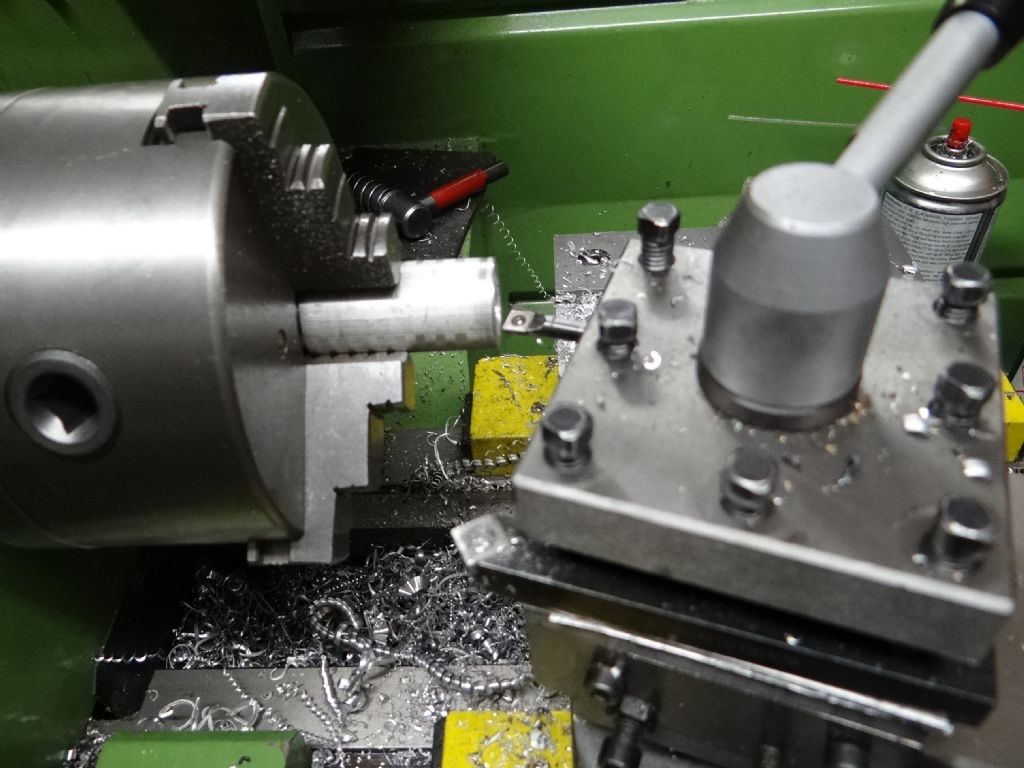
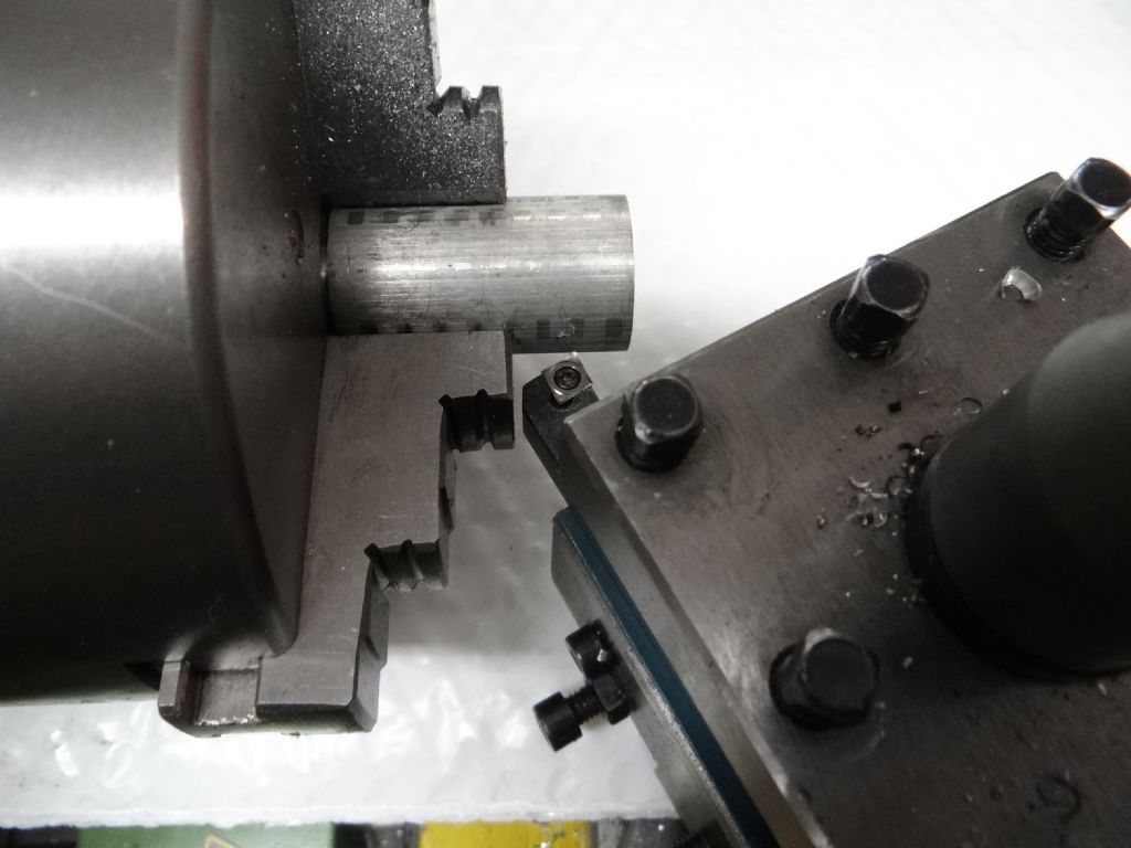
                                            Michael pointed out that my demonstration is flawed by me cutting a deep bevel rather than what was in Chris' spec. Quite right, it is harder to to cut a shallow bevel because the tool gets in the way. In this photo the top-slide is at maximum travel!

                                            dsc05925.jpg

                                            I was able to get close enough by increasing the tool overhang. Normally I like the cutting point to be as close to the tool-post as possible. It reduces the risk of chatter. However, chatter wasn't a problem in this case even with a long overhang.

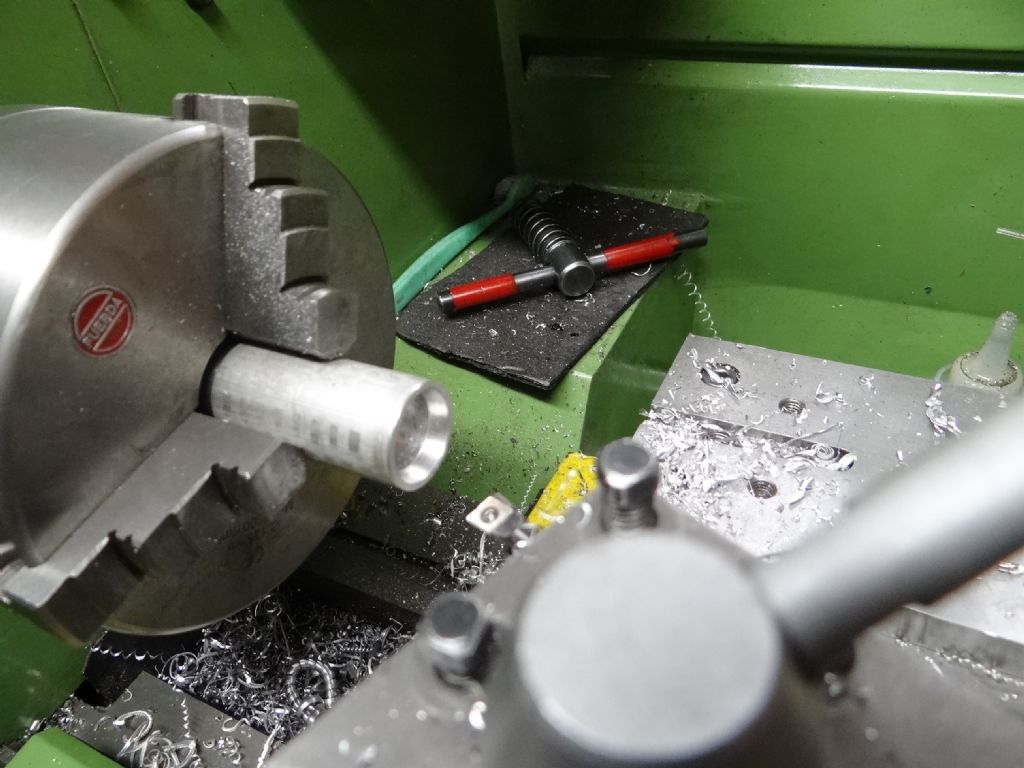
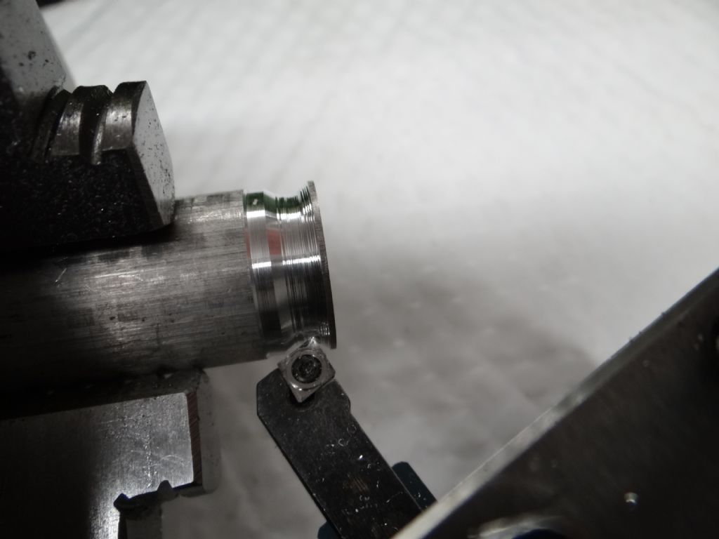
                                            Another consequence of lack of space due to the angle was that Duncan's point about cutting a groove came into play! In order to make space for the insert holder, I had to rough-out a groove in the rod before making the real cut.

                                            dsc05926.jpg

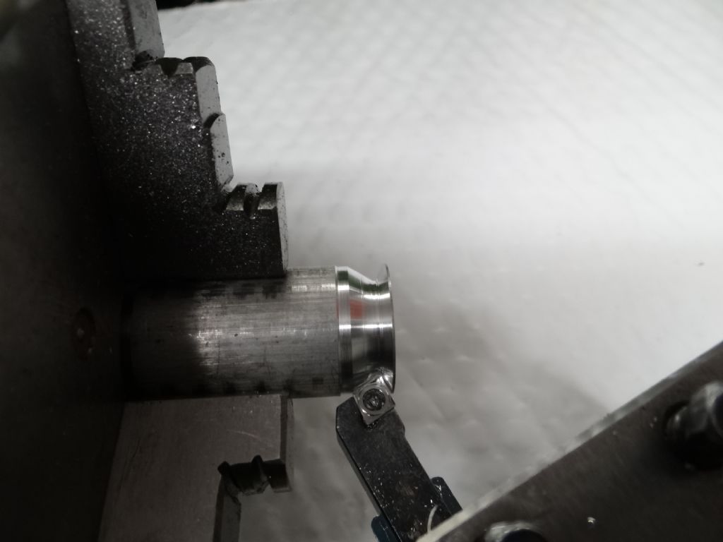
                                            It's helpful when grooving like this that carbide inserts can cut along the full length of their exposed edges, not just at the point. Finish cuts in the second stage. There was no need to part-off with another tool – I just cut into the bore.

                                            dsc05928.jpg

                                            By the magic of Gimp, two photographs of the finished item merged for top and bottom views:

                                            bothsides.jpg

                                            Other comments:

                                            Cutting the inner bevel was easy enough but I did need to use a boring bar to get clearance. With a silver aluminium insert there was no repeat of the chatter I got with an ordinary gold insert.

                                            At no time did I see signs of distress as the bevel got thinner.

                                            A disadvantage is the potential loss of accuracy due to having to position the tool with the Carriage Wheel. This has much coarser travel than the fine verniers on the top and cross-slides. Despite that I got to 0.63mm on a target of 0.6mm. It does make getting an accurate result slightly awkward though.

                                            Thanks to Chris for providing a 'not too much work' diversion from domestic duties. I should be recycling junk and washing floors…

                                            Dave


                                            Edited By SillyOldDuffer on 05/02/2019 14:16:50

                                            #394799
                                            Emgee
                                            Participant
                                              @emgee

                                              That's much better Dave looks about the same as the picture, well done.

                                              Emgee

                                              #394801
                                              Michael Gilligan
                                              Participant
                                                @michaelgilligan61133

                                                Apologies for any inconvenience caused, Dave

                                                MichaelG.

                                                [a.k.a. 'people']

                                                #394813
                                                duncan webster 1
                                                Participant
                                                  @duncanwebster1

                                                  You could also use one of those pointy inserts, but for cutting ally I'd use HSS

                                                  Edited By duncan webster on 05/02/2019 16:03:35

                                                  #394954
                                                  Neil Wyatt
                                                  Moderator
                                                    @neilwyatt

                                                    If anodising, use professional dyes, the results are much better if you want a good black.

                                                    I've experimented with using a mask, if you can print on the numbers in a resistant layer before dropping into the dye, then clean off the mask before sealing you will get a very durable result.

                                                    Neil

                                                    #394987
                                                    Christopher Buxton
                                                    Participant
                                                      @christopherbuxton96596

                                                      Thank you so much for the examples of what I need to achieve and the detailed pictures of the methods used.
                                                      My tube arrived today. Smallest amount I could order was 1m so I reckon I have about 300 goes at it before I run out of aluminium or patience.
                                                      Would anyone suggest a lubricant whilst cutting? I’ve read previous threads with so many different opinions.lathe speeds, type and shape of graver etc.
                                                      Going to have a crack at it on Sunday when the Mrs is at work and I can concentrate.
                                                      Think the angle issue is going to be trial and error as I don’t have very precise measuring equipment so I guess 0.1mm out could throw the angles out by degrees.

                                                    Viewing 25 posts - 1 through 25 (of 27 total)
                                                    • Please log in to reply to this topic. Registering is free and easy using the links on the menu at the top of this page.

                                                    Advert

                                                    Latest Replies

                                                    Home Forums Beginners questions Topics

                                                    Viewing 25 topics - 1 through 25 (of 25 total)
                                                    Viewing 25 topics - 1 through 25 (of 25 total)

                                                    View full reply list.

                                                    Advert

                                                    Newsletter Sign-up