CNC engraved tool rack

Advert

CNC engraved tool rack

Home Forums Workshop Tools and Tooling CNC engraved tool rack

Viewing 11 posts - 1 through 11 (of 11 total)
  • Author
    Posts
  • #389729
    Rik Shaw
    Participant
      @rikshaw

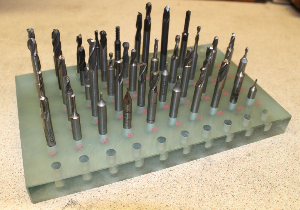
      Just finished making a numbered tool rack for my CNC mill from a “perspex like” material. This was my first attempt at CNC engraving. The “perspex” to my surprise was not flat enough to engrave so I found it necessary to fly cut it flat on the big mill before starting. To give an idea of size the tools are 6mm / .250” diameter.

      perspex.jpg

      Doing the numbering here:

      **LINK**


      Rik

      Edited By JasonB on 06/01/2019 19:02:58

      Advert
      #19197
      Rik Shaw
      Participant
        @rikshaw

        …….a place for my cutters

        #389752
        David George 1
        Participant
          @davidgeorge1

          Hi Rick nice job did you cut the holes on same machine.

          David

          #389768
          Rik Shaw
          Participant
            @rikshaw

            Hello David – No I did not drill the holes on the CNC. What I did do and what the movie did not show is that the hole positions were spotted with the engraver cutter after the numbers were engraved and were then drilled on my bench drill afterwards. Thanks for your interest.

            Rik

            #389796
            Martin Connelly
            Participant
              @martinconnelly55370

              I am curious to know why you did not drill the holes with the CNC mill. A rectangular array of drilled holes like that looks like a job that really suits CNC.

              Martin C

              #389818
              Rik Shaw
              Participant
                @rikshaw

                Martin – Thanks for your interest. I didn’t do the drilling on the CNC as I have not yet worked out how to include tool changes in a machining sequence. The hole positions were just spotted using the same engraving cutter after the numbers had been engraved. This was my first opportunity to do useful work with the machine and I was impatient to see a result.

                Impatience rewarded its now back to the learning curve – more like a vertical climb – phew!

                Rik

                #389828
                Martin Connelly
                Participant
                  @martinconnelly55370

                  Like lots of other things CNC seems hard until you have figured it out, then you think why did it seem so hard. Some things are easier to learn with someone walking you through the process but by far the best way to learn is to do it yourself. Often all you need to know is that something can be done so you are not going down a blind alleyway.
                  Martin C

                  #389830
                  JasonB
                  Moderator
                    @jasonb

                    What are those higher speed spindles like for drilling plastics, is there a chance of melting things?

                    #389840
                    Adam Mara
                    Participant
                      @adammara

                      JasonB, when I was at work, I used a Gerber Dimension 200 router with a Perske high speed motor, never had a problem with acrytlic melting , we used end mills and slot drills as required. As to acrylic not being flat, we always have a problem laser engraving jobs involving mortice and tenon joints, as they are often to tight, or loose due to variations in thickness.

                      #389848
                      Anonymous

                        For plastics I tend to run at the same spindle speeds as steel, but increase the feedrate by 4 or 5 times. On the Bridgeport I simply use the 'rapid' button rather than faff around with the feedrate control.

                        The main issue with tool changing is accounting for the offset in length between tools. To set the scene I assume that we don't have an automatic tool changer and that the spindle has a repeatable chucking mechanism, ie, the tool always goes back in the same place in terms of Z. If it doesn't then all bets are off.

                        Of course the exact command sequence will depend upon the control system. But the basic G-code for a tool change without offsets is:

                        T01 M06

                        This asks for tool 1 (really aimed at an autochanger selecting the tool in advance) and M06 instructs the system to load tool 1. On my CNC mill the program simply stops at this point, one changes the tool manually and then hits the 'cycle start' button. But before doing so you need to change the Z value to reflect any difference in tool length. I used to do this manually. The first time I ran a program I would reset the Z=0 reference with each tool change and write down the offset. Then at each subsequent run I'd just type the numbers in as required. This got tedious for two reasons. One I got fed up chipping carbide cutters when touching off on the work or fixture. Two, if you forget to type in the number the results can be spectacular. Like burying a M3 tap 20mm into the hole before the spindle has started. embarrassed

                        For these reasons I started using tool offset tables and also bought an electronic tool height setter. I use a master tool as tool 0 and use that to set the fundamental Z=0 reference. Then I use the tool setter to semi-automatically fill the tool table with the offset of each tool in turn relative to tool 0. The tool table can also be filled by measuring the tool lengths off line and typing in the numbers. The code for a tool change with tool table is:

                        T01 G43 H01 M06

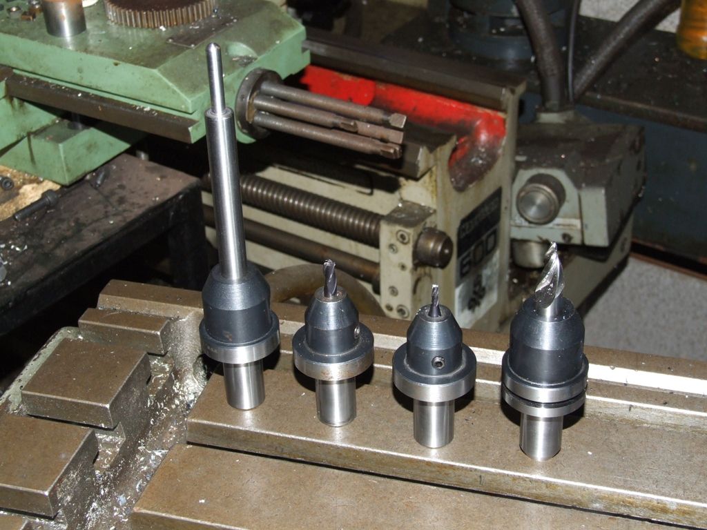
                        As before, except the G43 tells the system that rhe tool offset is positive, ie, added. The actual tool offsets in my tool table are negative as the tools are all shorter than the master tool 0. Tool 0 is the one on the left:

                        cnc_tooling.jpg

                        The H01 tells the system to look up the offset entry in the tool table for tool 1. In theory simple, but the hand hovers over the emergency off the first few times!

                        Andrew

                        #389850
                        JasonB
                        Moderator
                          @jasonb

                          Thanks for the replies, I just though there may of been speed issues as the suggested drilling speed for that plastic is 30-50m/min and with a spindle that probably does 5000rpm at it's slowest setting you would be doing the 1/4" holes at 100m/min.

                          Not such an issue on the Bridgeport or Tormack as they don't run as fast.

                        Viewing 11 posts - 1 through 11 (of 11 total)
                        • Please log in to reply to this topic. Registering is free and easy using the links on the menu at the top of this page.

                        Advert

                        Latest Replies

                        Viewing 25 topics - 1 through 25 (of 25 total)
                        Viewing 25 topics - 1 through 25 (of 25 total)

                        View full reply list.

                        Advert

                        Newsletter Sign-up