A while ago I mentioned the odd effect of the headstock oiler. When running the oil level in the cup rises, but when the spindle is stopped it drops significantly. Several readers confirmed their lathe did the same. I found the answer in a textbook recently and the reason is very interesting and has an important message about oilers and where on a bearing housing they should be.
In the 1860s hot axle boxes on locos and rolling stock was a common problem and several changes were made to alleviate the problem. One was to cut an oil well into the bottom of the axle box bearing to hold oil. But this didn't solve the problem. A British railway engineer Beauchamp Tower decided to investigate the problem.
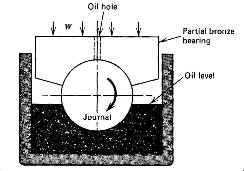
In a railway axle box the axle shaft only contacts the top surface of the bearing, it never contacts the bottom of the bearing. So the oil well should be the ideal place to place it. Tower discovered that oil was squeezed out from the bearing when spun at high speed. To resolve the problem he made a simple test apparatus which is shown here.

Tower drilled an oiler hole in the top of the bearing intending to try different oilers. However, he stuffed a cork into the hole as he wasn't at that stage in the experiments. When he spun up the axle the cork popped out! He hammered it in and it did the same thing. He then used a piece of wood and hammered it in good and hard. It was blown out like a champagne cork when the axle was spun up to speed. He then attached a pressure gauge and was amazed at the pressure indicated.
The reason is that the axle shaft in a plain bearing sleeve always runs eccentrically as they has to be a small clearance between the shaft and the bearing. The shaft when stationary will contact the bearing and any oil present will be squeezed out due to the weight on the bearing. When the shaft begins to rotate any oil will be dragged around until the shaft reaches a certain minimum speed and then it forms a wedge of oil which is passing from a large gap to the small gap between the shaft and stationary bearing. The shaft then "floats" on the oil with no metal to metal contact.
It works in the same way as a water skier waiting to be towed. When the boat begins moving the skier leans back holding the rope and the skies are pointed upwards at an angle and as the speed increases the skies ride up through the water until they are sliding across the top of the water. This supports the skier by generating a high pressure region due to the wedging action of the liquid.
So it should be obvious that an oiler must not be placed at a high pressure point in a bearing unless the oil is fed in under pressure to overcome the pressure generated by the shaft rotating. Liquid will always flow from a high to low pressure region.
In America in the early railroad days it was common to need two or more locos to get a long and heavy train moving. But when the speed was above a certain limit the oil begins to float the axle shaft and the friction drops considerably. Below a certain speed the bearing is in metal to metal contact and has high friction, but once the speed rises the oil film begins wedging and building up pressure and the axle rise off the bearing and floats on the oil. This known as hydrodynamic fluid motion.
So the oil in a plain axle box is often held in felt pads in the bottom of the box so that a small but constant supply of lubricant is wiped onto the shaft but preventing the pumping action which empties the oil box. The oil is poured into the box with the shaft stationary by a filler cum level plug below the axle shaft.
With the invention of rolling bearings (ball and roller types) the friction in the axle bearings was reduced dramatically and starting long trains was not as big a problem.
So the Myford headstock oiler with the wick is doing exactly which is required as it is in a low pressure region of the bearing and the spindle builds pressure pushing the oil back to the oil cup. But the wick provides adequate oil with the wiping action to supply the bearing.
Edited By John Fielding on 19/03/2016 07:24:24
John Fielding.


 thank you for sharing this.

