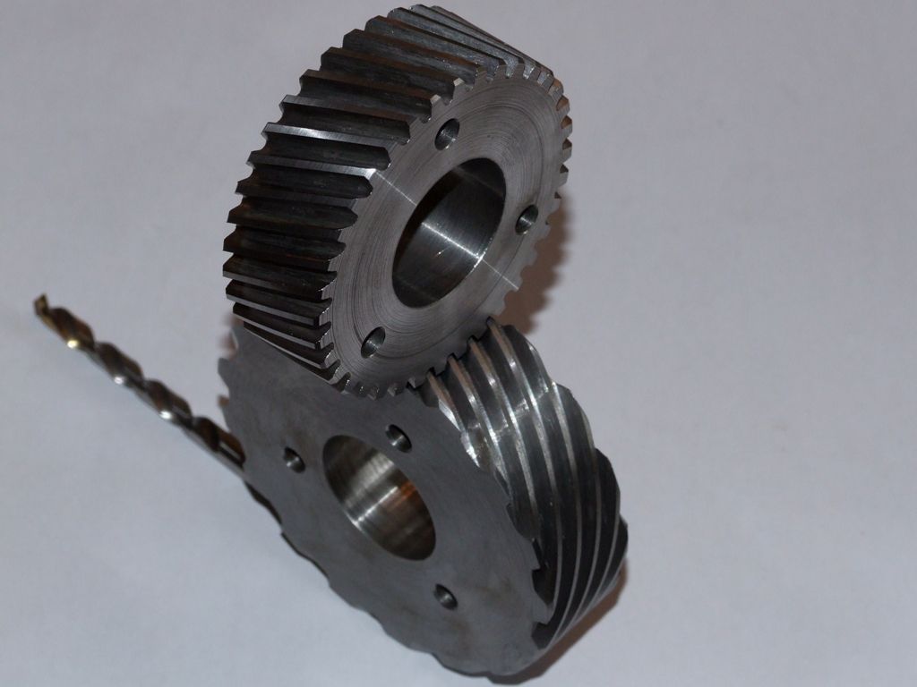
I moved onto internal gears today; not surprising as it was the sort of 'orrid day to stay inside. Over the last few days I've been designing an internal gear and pinion, creating the involute curve and building the gears up from that in 3D CAD. I also 3D printed the gears to check operation. Here are the printed gears, steel gear blanks and an arbor to hold the pinion:

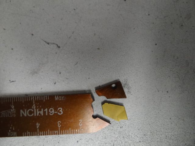
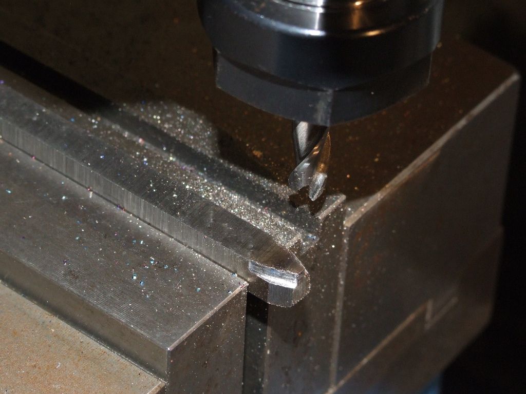
To create the tool for the slotting head I created a profile in 3D CAD, transfered it to CAM to generate G-code and CNC milled the shape on the end of a toolbit. I partially ground the toolbit away prior to milling and only milled the profile 2mm deep as the rest will be ground away to create reliefs:

The toolbit was ¼" square HSS; no problem milling it using the same speeds and feeds as I used for low carbon steel, bur with a smaller DOC.
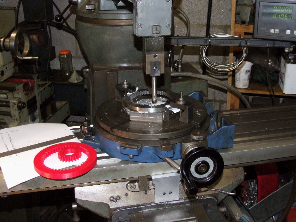
There is quite a lot of tedious setting up prior to cutting the teeth on the internal gear, but the basic operation is fairly standard involving the rotary table. I chose to make a gear with 45 teeth as it simplifies the indexing:

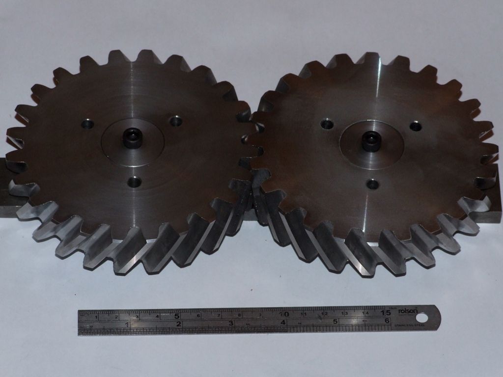
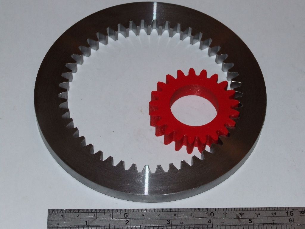
The DRO is used in Y to set the depth of cut for each tooth. On the left is an Excel generated crib sheet with the angles that I needed for each tooth, as a double check. I had some issues with the tool moving in the slotting head holder. So I ground a small groove in the bottom of the tool so that the set screw could postively locate the tool. Except that the set screw then became loose during each cut.  So I fitted a locknut to the set screw. After cutting all the teeth I went round again, just for good measure, to check that the depth of cut was the same for each tooth. Here's the finished gear and 3D printed pinion, which seems to rotate smoothly:

Note there is no rounding of the internal ends of the involute curves.  At some point over the next few weeks I will make the pinion in steel, so that I have a matching set.
I've had supper, but I can't resist another helping of home made, and home grown, plum and gage oatmeal crumble and yoghurt, plus a glass of wine. 
Andrew
 JasonB.

