What Did You Do Today (2016)

Advert

What Did You Do Today (2016)

Home Forums The Tea Room What Did You Do Today (2016)

Viewing 25 posts - 1,576 through 1,600 (of 2,143 total)
  • Author
    Posts
  • #262629
    Daniel
    Participant
      @daniel

      Great photo Bazyle yes


      Edited By Daniel on 23/10/2016 22:43:54

      Advert
      #262797
      Gray62
      Participant
        @gray62

        Put the Boxford shaper to good use tonight to put the keyway slots in the spacers for a new 40int horizontal arbor I made for the Ajax mill

        It's not polished shiny to within a sub micron of its life but it works, runs true and fulfils its purpose (and didn't cost and arm and a leg!)

        Arbor and spacers

        #262801
        John Stevenson 1
        Participant
          @johnstevenson1
          Posted by Andrew Johnston on 23/10/2016 10:32:05:

          It is interesting to note that the 3D printed gear set has an assembly issue. The gears mesh properly, but cannot be assembled properly by pushing them together in the same plane. Instead they need to be assembled axially. In reality when the 3D printed gears are assembled in the same plane they need a good push, and there is an audible click. I suspect that metal gears, with less 'give', wouldn't assemble.

          Andrew

          Andrew,

          I have noticed the same thing and when I measure across the gear using pins, I find that they are a tad big so now I start off printing to 0.97 scale and get far better results but it is a bit suck it and see.

          #262805
          Anonymous
            Posted by John Stevenson on 24/10/2016 20:36:26:

            I have noticed the same thing and when I measure across the gear using pins, I find that they are a tad big so now I start off printing to 0.97 scale and get far better results but it is a bit suck it and see.

            That's interesting; when I first got my 3D printer I did a lot of experiments with 25mm cubes and it seemed to print slightly small. If I recall correctly the parts were 1-2% undersize, and it varied with axis. The Z axis was different to X and Y. I put the size differences down to the plastic shrinking slightly as it cooled, and the printing process being anisotropic..

            I've just measured the OD of the internal gear. It should be 6", as that is the diameter of the metal stock I bought to make a real one. The plastic version measures 5.93" or thereabouts. So a bit over 1% small. May be I should try measuring the internals of the internal gear. I agree that it is quite a lot suck it and see. All part of the learning process.

            I think that the refusal to mesh, except axially, is a feature of internal gears rather than a consequence of my printing technique? Once I've made a real internal gear I'll try and obtain an understanding of the interference issues and when they occur. I think that it is safe to say though that most problems occur with a relatively small number of teeth on the internal gear and/or when the number of pinion teeth are a significant proportion of the internal gear number.

            Andrew

            #262812
            Anonymous

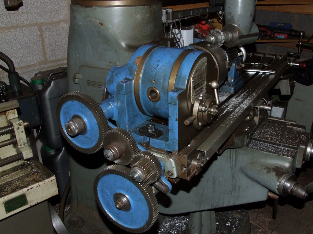
              This evening I made a high helix helical gear, just for fun. Since I don't have a universal milling head for the horizontal mill I used the right angle head on the Bridgeport. Here's the basic set up, complete with the wrong hand dividing head (I'm nothing if not consistent):

              high helix gear setup.jpg

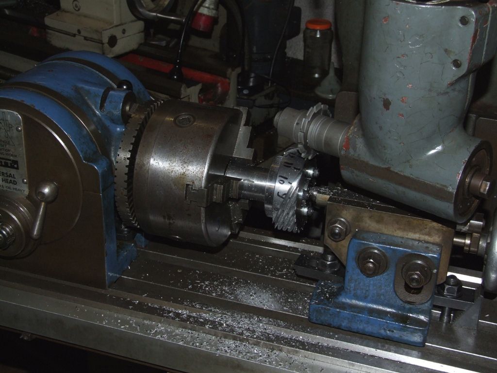
              I had to make an adaptor, with internal and external keyways, to fit the large gear at the bottom on to the mill table leadscrew. Since I never use a handle on this end of the table the adaptor can stay there. Here's a close up of the gear blank and cutter:

              high helix gear cutting.jpg

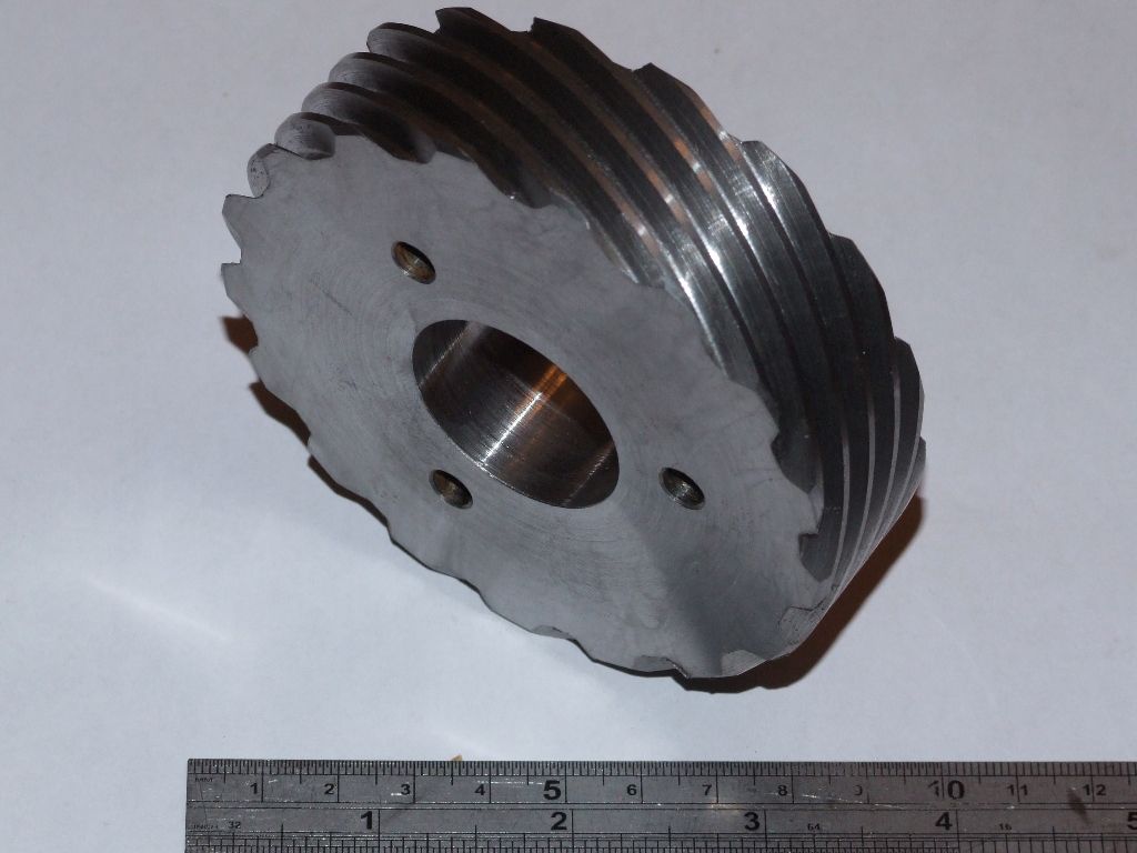
              Note the felt tip pen numbers on the gear blank. I like to check the indexing before cutting metal – been there, done that, got it wrong. The gear is 17 tooth, 14DP with a helix angle of 70º. These are just convenient numbers to avoid overloading the right angle drive while allowing me to salvage the blank from the disaster area that was my first attempt at cutting a helical gear. Here is the final gear:

              high helix gear.jpg

              That's it now for helical gears, at least for the time being. I think I now understand the basic maths and have proved to myself that I can make helical gears using old school methods. At some point in the future I might have a go at making one on the CNC mill. I know I can cut helical features on the CNC mill, and I understand the maths, so it should simply be a case of grinding through the trignometry to position the cutter for each pass.

              Onwards to internal gears now! Actually the next thing to do is sort out the DRO on the Bridgeport, as one of the axes seems to have stuck it's feet in the air. The display says 'no sig' and the error moves with the sensor, so it's not the display. I've been through the manufacturers diagonstics and when they get to the bit where the display gives 'no sig' they say it's ****ed, and to send it back. I think that the sensor head is potted, so it's probably a case of buying a new one. I need to remove it anyway so I'll do a basic check and see if there are any loose or damaged wires before contacting tech support.

              Andrew

              #262826
              Neil Wyatt
              Moderator
                @neilwyatt

                I bet if you round the corners of the internal teeth as if they were the roots of the tooth spaces on an external gear, you will be able to assemble them

                Today I tried using photo-resist film. the supplied instructions were totally useless – they didn't mention you need heat to get the film to stick!

                Try 1 – whole film turns purple. UV doesn't make it come off???

                Try 2 – same problem – realise it's too much heat, I realise now that if the film turns purple it has overheated.

                Try 3 – use less heat, but when put in the developer the result is negative! This film turns hard when exposed to UV, while the spray/pre-treated boards I use its the UV-exposed bits that disappear in the developer.

                Try 4 – use negative artwork. Is it etching? it hasn't gone the usual pink… back in the developer Oh dear all the resist has started to come off… oh look you can see where it's etched a bit, but somehow this type of brass doesn't go salmon pink!

                Try 5 – This should be perfect. oops didn't hear the timer because I picked up my guitar. Looks like it's developing OK… except all along that side where it's all over-exposed.

                Try 6 – at last! A decent mask, in the etch at last!

                I'm glad I decided to practice on a 30mm disc before trying the 240mm one…

                Tomorrow, find the exposure time under fluorescent lights – my UV box is only 6" wide…

                Neil

                #262833
                John Stevenson 1
                Participant
                  @johnstevenson1
                  Posted by Andrew Johnston on 23/10/2016 10:32:05:

                  It is interesting to note that the 3D printed gear set has an assembly issue. The gears mesh properly, but cannot be assembled properly by pushing them together in the same plane. Instead they need to be assembled axially. In reality when the 3D printed gears are assembled in the same plane they need a good push, and there is an audible click. I suspect that metal gears, with less 'give', wouldn't assemble.

                  Andrew

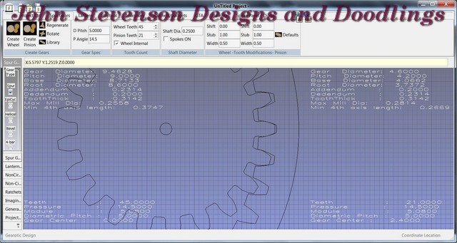
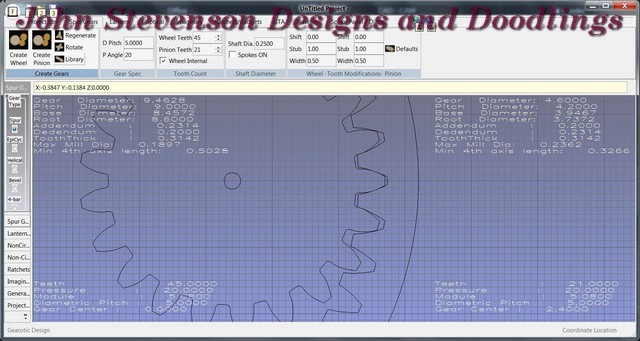
                  Andrew at 14.5 degree Pa you are going to get interference when pushing the two gears together.

                  Look where the top of the internal tooth, one above centre is making contact with the spur gear. These are your figures of 21 / 45. I have modeled in 5DP but the DP doesn't affect the fit, only the size.

                  Now if we do this at 20 degrees it's a lot better.

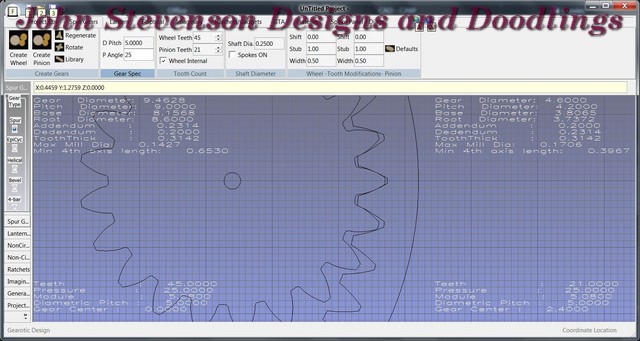
                  However because it's a known problem that gets worse the closer the two gears get to each other in number it's quite common for internal gears to move up to 25 PA and even 30 PA in extreme cases.

                  This is 25 PA.

                  Far stronger teeth and less interference all round.

                  #262847
                  JasonB
                  Moderator
                    @jasonb

                    Helical Gear looks good Andrew, you will have to start a sideline making pairs of helical gears for the side rod open crank engines like Westbury's Centaur and Wyvern as the original spec gears are not available.

                    J

                    #262858
                    Anonymous
                      Posted by Neil Wyatt on 24/10/2016 22:35:59:

                      I bet if you round the corners of the internal teeth as if they were the roots of the tooth spaces on an external gear, you will be able to assemble them

                      Have you considered therapy to help with this irrational desire to fillet involute tooth forms? It might be worthwhile before you get a visit from the boys at SPRIC, who could fillet you.

                      Andrew

                      SPRIC – Society for the Protection of Real Involute Curves

                      #262875
                      Russell Eberhardt
                      Participant
                        @russelleberhardt48058
                        Posted by Neil Wyatt on 24/10/2016 22:35:59:Today I tried using photo-resist film. the supplied instructions were totally useless – they didn't mention you need heat to get the film to stick!

                        What film are you using. I used Mungolux and found it to work well but care is needed:

                        dscf2661.jpg

                        dscf2666s.jpg

                        Yes, heat is needed to make it stick. At first I tried a domestic iron through a brown paper sheet but had inconsistent results. I have found that a couple of passes through a Lidl A3 laminator does the trick. You do have to make sure that there are no bubbles after you use the squeege. It is easy to get wrinkles in the film otherwise and the etchant can creep under it.

                        Take care not to over-expose otherwise, after developing, almost invisible traces of film can be left and leave un-etched areas. I found that 3 seconds of sunlight at midday in November worked well. Sunlight has the advantage that the rays are parallel and give sharper edges.

                        If you haven't seen it this video is worth watching.

                        Russell

                        #262883
                        Anonymous

                          Thanks John; intuitively that is what I would expect. The DP is simply a uniform scaling factor, so has effect. I would expect the problem to ease with higher pressure angles as the width of the gap at the top (inner) of the addendum will be wider.

                          I expect this has been modelled mathematically, and if so, I aim to ferret it out.

                          Andrew

                          #262890
                          Nigel McBurney 1
                          Participant
                            @nigelmcburney1

                            I have just set up my mill to cut a 63 T gear using differential indexing, I have a 100 mm centre height Hofman dividing head,I use the universally known Brown and Sharp tables in Machinerys handbook,the tables state the that for 63 T two idlers are required in the gear train to rotate the index plate, I would like to mention that for my Hofman head this does not work it only requires one idler,and if you are indexing another number which the table says use one idler the Hofman requires 2 idlers, I can only find an drawing of a B & s Head and cannot compare with the Hofman so can only assume that there is an extra internal gear somewhere in the internal train.I do not have any instructions or manual with my Hofman head.

                            #262894
                            Bazyle
                            Participant
                              @bazyle

                              Interesting observation Nigel. Probably depends on what someone chose as LH or RH for the helix drive from the universal input shaft. I'll check mine tonight. The Elliott tables differ in a few places from B&S and I'd trust the latter more. I think 201 and 233 in the Elliott tables are wrong but I can't quite understand my notes now, not that I'm ever going to need those values.

                              #262899
                              Anonymous
                                Posted by Nigel McBurney 1 on 25/10/2016 12:15:52:

                                I have just set up my mill to cut a 63 T gear using differential indexing………….

                                When I cut 63 and 69 tooth gears for my traction engines I was idle (groan) and made a special division plate rather than set up for differential dividing.

                                I'm missing the extension spindle that fits in the back of the dividing head spindle, so it was quicker to make a division plate than an extension spindle.

                                Andrew

                                #262936
                                Neil Wyatt
                                Moderator
                                  @neilwyatt
                                  Posted by Russell Eberhardt on 25/10/2016 10:27:35:

                                  Posted by Neil Wyatt on 24/10/2016 22:35:59:Today I tried using photo-resist film. the supplied instructions were totally useless – they didn't mention you need heat to get the film to stick!

                                  What film are you using. I used Mungolux and found it to work well but care is needed:

                                  dscf2661.jpg

                                  dscf2666s.jpg

                                  Yes, heat is needed to make it stick. At first I tried a domestic iron through a brown paper sheet but had inconsistent results. I have found that a couple of passes through a Lidl A3 laminator does the trick. You do have to make sure that there are no bubbles after you use the squeege. It is easy to get wrinkles in the film otherwise and the etchant can creep under it.

                                  Take care not to over-expose otherwise, after developing, almost invisible traces of film can be left and leave un-etched areas. I found that 3 seconds of sunlight at midday in November worked well. Sunlight has the advantage that the rays are parallel and give sharper edges.

                                  If you haven't seen it this video is worth watching.

                                  Russell

                                  Thanks Russell

                                  I wish I had found that video he's effectively doing EXACTLY what I want to do – even the same size and thickness of plate it seems!

                                  Neil

                                  #262974
                                  Brian H
                                  Participant
                                    @brianh50089

                                    I'm in the process of sorting out the electrics on my Boxford AUD because the lathe was converted to single phase some time before I bought it about 14 years ago.

                                    I bought a Vertex coolant set about 10 years ago so I thought that I ought to get that fitted as well.

                                    I'm searching ebay etc for a forward-stop-reverse switch and a switch to turn the coolant motor on and off.

                                    I managed to move the lathe away from the wall so that the pump etc can be fitted and expected to find all the items that I have lost over the years but all I found was swarf that had fallen down the back. I am also fitting a splashback so that shouldn't happen again!

                                    #262979
                                    Brian H
                                    Participant
                                      @brianh50089

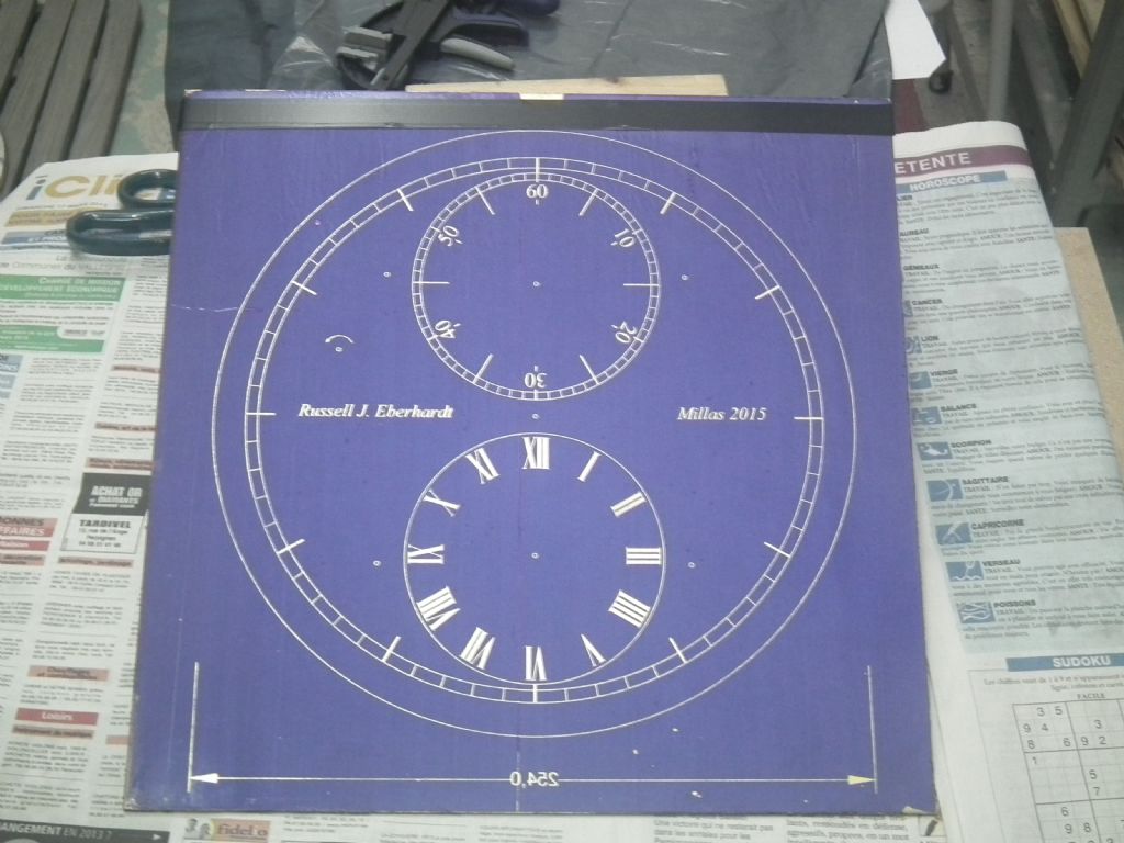
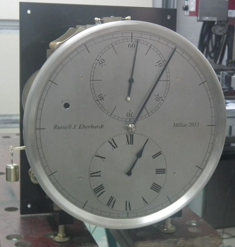
                                      I was interested in the making of a face for John Wildings English Regulator Clock as I made one of these some years ago. Mind you, I was lucky with the face; the firm I worked for had taken delivery of a very large and very expensive CNC engraving machine and I was friendly with the person who had been trained to operate it!  The machine took all of 8 minutes to cut the circles and roman numerals, the only problem being that we didn't know how the put curved lines at top & bottom of the numbers, so I had to make do with straight ones.

                                      Yes, cheating I know but………

                                      Edited By Brian Hutchings on 25/10/2016 21:00:58

                                      #262994
                                      Bazyle
                                      Participant
                                        @bazyle

                                        Further to my post above with my Elliott dividing head which is similar to a B&S when the universal input shaft is rotated the chuck rotates in the same direction.

                                        #263125
                                        ChrisH
                                        Participant
                                          @chrish

                                          Not today but yesterday and the day before.

                                          Replaced the top variator drive belt (at great expense) of the variator drive on my lathe. Only needed to strip the whole headstock down, which meant slackening the rear and front bearings off and driving the shaft out with a 1 1/2lb hammer and brass drift and trying not to loose bits into the oil bath for the drive to the leadscrew and power feed, then removing the back gear drive underneath entirely, and finally the variator pulleys which meant also removing the variator control so I could see what I was doing as the variator is up in the middle of the lathe, all hidden. And then putting it all back together again. With fresh oil and grease as required.  And not getting oil or grease on the belts in the process.

                                          The front headstock bearing is a double taper roller bearing back to back and the rear bearing a taper bronze sleeve bearing. Getting the front bearing set up right is an art, getting it tight enough to ensure no end play and freedom for parts to rotate that shouldn't – how do you ensure that when when you have no feel as it has to be driven in? – and not too tight so the bearing overheats? (The bearing temp can rise to 120 deg.F in real money (or 50 deg.C in new fangled foreign stuff) over an hour working max).

                                          But it's done now and the lathe is operational again.

                                          Chris

                                          Edited By ChrisH on 26/10/2016 21:39:38

                                          #263136
                                          Cornish Jack
                                          Participant
                                            @cornishjack

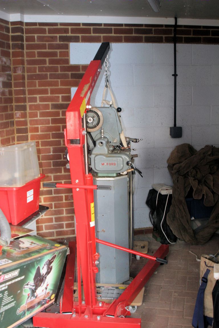
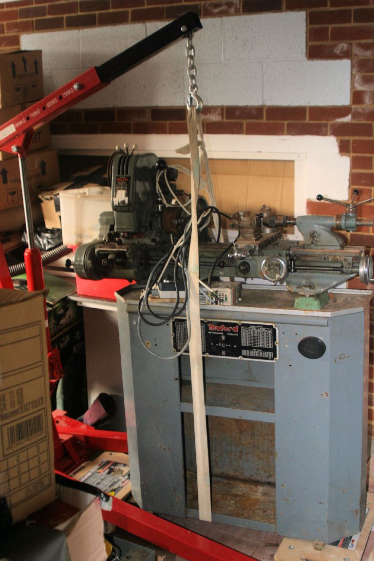
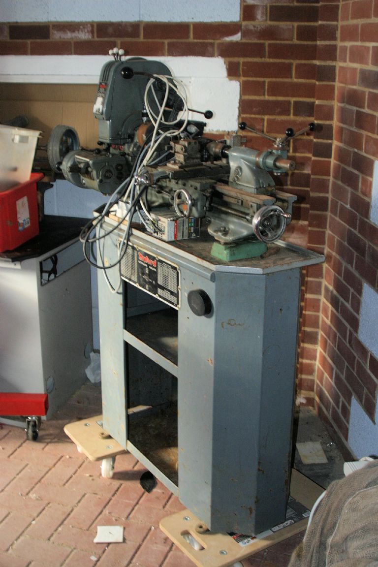
                                            Decided to 'bite the bullet' and make the Myford mobile, so I can more easily get at the VFD/motor setup , to reinstate it … so

                                            img_9112.jpg

                                            img_9113.jpg

                                            and

                                            img_9115.jpg

                                            Now securely mounted on a pair of Lidl's 'Pensioner's Skateboards' – excellent value MDF boards with 4 castors on each. Can now move it into the garage, from the carport, to work in comparative comfort.

                                            The hardest bit was erecting the engine lift – 80+ years and a knackered knee and back are not a good recipe for heaving large section metal about!!sad

                                            By my reckoning that's about .001% of the workshop reinstatement completed!

                                            rgds

                                            Bill

                                            #263138
                                            julian atkins
                                            Participant
                                              @julianatkins58923

                                              I went to the new Royal Mint 'experience' and exhibition at Llantrisant today.

                                              I am not a coin collector but thought it quite an excellent new attraction in South Wales, and well worth a visit.

                                              Cheers,

                                              Julian

                                              #263143
                                              duncan webster 1
                                              Participant
                                                @duncanwebster1

                                                Finished drilling over 300 holes for linking the rails for track circuiting at our club. Am I glad that's over! Question, why don't they put the handle on electric drills in line with the drill, it would get rid of that twisting action on your wrist.

                                                #263152
                                                Sam Longley 1
                                                Participant
                                                  @samlongley1
                                                  Posted by Cornish Jack on 26/10/2016 23:42:14:

                                                  Decided to 'bite the bullet' and make the Myford mobile, so I can more easily get at the VFD/motor setup , to reinstate it … so


                                                  and

                                                  img_9115.jpg

                                                  Now securely mounted on a pair of Lidl's 'Pensioner's Skateboards' – excellent value MDF boards with 4 castors on each. Can now move it into the garage, from the carport, to work in comparative comfort.

                                                  The hardest bit was erecting the engine lift – 80+ years and a knackered knee and back are not a good recipe for heaving large section metal about!!sad

                                                  By my reckoning that's about .001% of the workshop reinstatement completed!

                                                  rgds

                                                  Bill

                                                  With all due respects – that looks like a lathe just dying to fall overcrying

                                                  Edited By Sam Longley 1 on 27/10/2016 08:06:39

                                                  #263154
                                                  Bob Rodgerson
                                                  Participant
                                                    @bobrodgerson97362

                                                    I would have chosen a better base than MDF and heavier castors. When I decided to make my lathe and mill mobile I made two purpose built trolleys from 4" channel and 500kg castors that have an adjustable foot so that once in place they can be extended to stop the machine from moving.

                                                    Looking at Cornish Jacks efforts there could be a point where the wheels swivel in towards each other and then the wheelbase becomes much narrower, a wheel gets caught in a crack in the floor and over it goes.

                                                    #263163
                                                    Andy Pugh
                                                    Participant
                                                      @andypugh44463
                                                      Posted by Neil Wyatt on 25/10/2016 18:10:31:

                                                      Posted by Russell Eberhardt on 25/10/2016 10:27:35:

                                                      If you haven't seen it this video is worth watching.

                                                      Russell

                                                      Thanks Russell

                                                      I wish I had found that video he's effectively doing EXACTLY what I want to do

                                                      This one might be even better, if you aren't already following Clickspring:

                                                    Viewing 25 posts - 1,576 through 1,600 (of 2,143 total)
                                                    • Please log in to reply to this topic. Registering is free and easy using the links on the menu at the top of this page.

                                                    Advert

                                                    Latest Replies

                                                    Home Forums The Tea Room Topics

                                                    Viewing 25 topics - 1 through 25 (of 25 total)
                                                    Viewing 25 topics - 1 through 25 (of 25 total)

                                                    View full reply list.

                                                    Advert

                                                    Newsletter Sign-up