WARCO WM-250 lathe family and WM16 mill

Advert

WARCO WM-250 lathe family and WM16 mill

Home Forums Workshop Tools and Tooling WARCO WM-250 lathe family and WM16 mill

Viewing 25 posts - 26 through 50 (of 140 total)
  • Author
    Posts
  • #163558
    Ed Duffner
    Participant
      @edduffner79357

      Hi Martin, sorry for the delayed reply. When I'm tramming my WM16 and the head is ready to tighten, I use the small Allen screw on the right hand side of the head, near the top and adjust it to where it's just bearing against the head. This will help prevent the head rotating as you tighten the main securing nuts. I also tend to go back and fore between the two, tightening a bit at a time on each.

      Ed.

      Advert
      #163641
      Rik Shaw
      Participant
        @rikshaw

        I am in the throes of relocating to a bigger workshop and I am at the measuring up stage. Could someone who has a WM16 mill tell me how high (approx.) the machine is with the Z wound up as far as it will go. I would do it myself but I have a shelf above it which restricts me height wise and I am not yet ready to move it. Thanks

        Rik

        #163658
        Ed Duffner
        Participant
          @edduffner79357

          Rik,

          On its base stand It's 1750mm (~ 69 inches) from floor to top of the Z at full height. It's 940mm (~ 37 inches) from base of the mill to the top of the Z at full height.

          Cheers,
          Ed.

          #163676
          Ed Duffner
          Participant
            @edduffner79357

            Rik,

            I got that slightly wrong for a standard setup sorry. My machine has 0.5" rubber pads in between the floor and cabinet and again underneath the machine so correct dimensions would be:


            Full height = 1725mm (~ 68.0" )

            Machine height only = 927.5mm (~ 36.5" ) (Warco list it as 930mm)


            Ed.

            Edited By Ed Duffner on 16/09/2014 08:10:16

            Edited By Ed Duffner on 16/09/2014 08:17:09

            #163703
            Rik Shaw
            Participant
              @rikshaw

              Thanks Ed, most helpful of you. The mill will fit just where I want it to go in its new home.smile

              Rik

              #163715
              mechman48
              Participant
                @mechman48

                Hi Martin

                Look in my album under the workshop 'misc.' tab & you'll see a pic of one of the two little blocks made to align head when I trammed mine, adjusting ea. to centralise with dti, once aligned to dti just lock the locking nut & that should be it.

                George

                #181990
                Ed Duffner
                Participant
                  @edduffner79357

                  George,

                  May I ask what power source you used for your X axis auto-feed please?

                  I've received a used electric window motor today (Peugot 307) with a PWM controller somewhere en-route from Ebay with similar specs to yours and I'm thinking about load current and start current etc.

                  Thank you,
                  Ed.

                  #181999
                  mechman48
                  Participant
                    @mechman48

                    Like you I used a window winder from a scrap car, can't remember which, but without removing the drive & checking with a multimeter ( if I can remember how to do it ) I can't give you any figures re. load & start current, 'nuff to say that the fuse supplied in the PWM ( 3A ) hasn't blown yet & the motor runs quite cool all the time.

                    I'm sure one of our more electrickery savvy members would proffer meter set up to check current, & remind me too.

                    Have found the description of the PWM…

                    Descriptions:

                    • This CCM2NJ motor speed controller adopts a high power MOSFET with a heat sink and can easily provide a continuous current of 3A to your DC motor or other DC load, high power, high efficiency, large torque, with switch function.
                    • Onboard 10A fuse, with Reverse power,Overvoltage, high current protection function, power on LED indicator

                    George

                    Edited By mechman48 on 03/03/2015 17:13:45

                    #182036
                    Ed Duffner
                    Participant
                      @edduffner79357

                      Thank you George, most appreciated.

                      #182047
                      Michael Gilligan
                      Participant
                        @michaelgilligan61133
                        Posted by Ed Duffner on 01/08/2014 17:06:27:.

                        I'm curious to understand how a two wire motor can be operated by a PWM control. I thought the motor had to have some sort of additional wiring to send EMF back to the electronics.

                        .

                        Ed,

                        PWM = Pulse Width Modulation

                        Works very well indeed on ordinary permanent magnet DC motors.

                        Here is a reasonable introduction.

                        MichaelG.

                        Edited By Michael Gilligan on 03/03/2015 23:07:09

                        #182052
                        Ed Duffner
                        Participant
                          @edduffner79357

                          Thank you for the link Michael, I'll have a good read of that as I've wondered how PWM works across 2 wires and how back EMF is detected etc

                          I was a sparky for 10 years but I think I only installed one DC motor starter in all that time so my knowledge of DC motors is limited.

                          I'm trying to determine what kind of power supply would be ok to drive the motor I have. There are a couple I've found today:

                          Switch mode PSU
                          **LINK**

                          Adaptor PSU
                          **LINK**

                          Measuring across the motor's 2-pin connector ( I assume the armature) I get 4.5 ohms which would work out at 2.6amps for a 12VDC supply and the PWM controller I have on order can supply a constant 3amps, similar to George's unit.

                          I know that in AC inductive loads there is an initial start current and as a rule of thumb was generally accepted as 1.8 times the running current. I'm unsure if DC has the same start current (inrush current is it?) characteristics hence the thoughts about, will the 3amp constant load of the PWM controller I'm getting be high enough to cope with any DC start current and would the switch mode or Adaptor type power supply be suitable.

                          I'm not expecting an answer (I probably ask too many questions on the forum) just sharing my thoughts.

                          Kind regards,
                          Ed.

                          #182072
                          Michael Gilligan
                          Participant
                            @michaelgilligan61133
                            Posted by Ed Duffner on 03/03/2015 23:54:35:

                            Thank you for the link Michael, I'll have a good read of that as I've wondered how PWM works …

                            .

                            I know that in AC inductive loads there is an initial start current and as a rule of thumb was generally accepted as 1.8 times the running current. I'm unsure if DC has the same start current (inrush current is it?) characteristics hence the thoughts about, will the 3amp constant load of the PWM controller I'm getting be high enough to cope with any DC start current and would the switch mode or Adaptor type power supply be suitable.

                            I'm not expecting an answer (I probably ask too many questions on the forum) just sharing my thoughts.

                            .

                            Ed,

                            Responding in reverse order:

                            • Of course you should expect an answer [from me and hopefully from others who are better-informed] … that's what the forum is for!
                            • The matter using switch mode power supplies to drive PWM controllers is an interesting one … in theory, there could be a problem of 'beats' occurring between the two operating frequencies; but I have never seen this in [my limited] practice. I would just try it.
                            • Yes, DC motors also have a higher inrush current, and if full voltage is applied at start-up you will see it. BUT one of the beauties of PWM is that you can gradually increase the effective voltage. … As you will hopefully have understood from the link that I posted; the peak voltage is always "full" but the effective voltage changes with the mark:space raio of the pulse wave.

                            Hope that all makes sense.

                            MichaelG.

                            Edited By Michael Gilligan on 04/03/2015 08:53:48

                            Edited By Michael Gilligan on 04/03/2015 08:54:53

                            #182078
                            Les Jones 1
                            Participant
                              @lesjones1

                              Hi Ed,
                              A PWM controller is not a closed loop speed control system so it does not need a separate feedback signal. For the IDEAL permenant motor the speed is proportional to the voltage and the torque proportional to the current. So under no load the back emf (This is from the motor working as a generator. Not from any inductive effect.) is equal to the supply voltage. In a real motor the windings have resistance so the speed will drop due to the voltage developed across this resistance means that the motor slows down until the back emf is equal to the supply voltage minus the voltage drop across this resistance. On you motor the stall current (Back emf = 0) will be 2.6 amps A simplified explanation of a PWM controller is that it provides an average voltage output that means that the speed will be roughly proportional to this average voltage. Normaly the winding resistance is quite low so that the voltage drop across the winding resistance is also quite low when the motor is running at its rated current. As the winding resistance of your motor is 4.5 ohms I suspect it will not be powerfull enough for your purpose.

                              Les.

                              #182086
                              Ed Duffner
                              Participant
                                @edduffner79357

                                Thanks again Michael and Les for your expertise

                                I think with the PWM reference I may have been confusing myself with multi phase stepper motor speed control which I've also been reading about recently.

                                Regards,
                                Ed.

                                #182574
                                Rik Shaw
                                Participant
                                  @rikshaw

                                  My WM250 VF lathe has always had a problem with the on/off switch pop popping until eventually it gets going and until now I have put up with it. However, having moved into the new workshop the lathes power now comes from a different consumer unit located in the new place and they don't like each other.

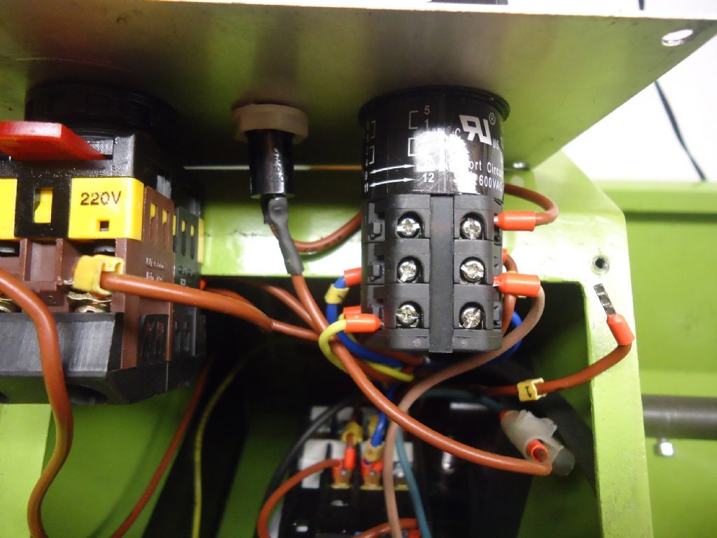
                                  The lathe is now unusable as every time I press the ON button it trips the breaker. So today I removed the four screws holding the front switch panel in place and squirted some contact cleaner where I thought it would do its best, worked the switch on and of a dozen times or so and replaced the panel.

                                  Turned power back on and hit the ON button – 'nuffing! Machine would not power up. Removed panel again and could see that a brown (live) wire had come adrift but from where?

                                  Maybe the switch cleaner has done its work and maybe it hasn't but until I know where that wire should go I'll not know. The only clue is that one of the empty terminal clamping screws on the forward/reverse knob is loose but without knowing for sure I am reluctant to avoid total meltdown in case I get it wrong.

                                  I know there is a circuit diagram on the rear of the headstock which I took a photo of when the lathe was being relocated but it is so blurred as to be unreadable. I am able – with difficulty – to move the lathe for another pic of the circuit diagram but there is a lot of weight involved and spinal surgery with a further slipped disc since is not exactly the incentive I need. Anyway, I am not a genius in the "sparks" department so maybe even a clearer schematic would have been wasted on me.

                                  All in all I think it has to be a replacement switch but I STILL need to know where the loose wire goes.

                                  Pulling the panel out it looks like this from above:

                                  wm250 switch top view.jpg

                                  From underneath it looks like this: (note the rogue loose wire).

                                  wm250 switch underside view.jpg

                                  Any help would be much appreciated.

                                  Rik

                                  #183334
                                  Rik Shaw
                                  Participant
                                    @rikshaw

                                    I am still having major issues getting my dead WM250-VF going. Its blowing fuses (front and back) and tripping the MCB (16A). Despite advice from WARCO and a selection (their choice) of various ON/OFF switches which differ from the original along with a replacement forward/reverse switch the lathe stubbornly refuses to run.

                                    They have promised delivery of yet another switch tomorrow which they assure me will be identical to the original fitted to my machine. I just hope that all this messing about with different switches has not caused collateral damage to other circuits/controllers.

                                    In the mean time though, if you have one of these lathes and can get to the rear of it would you be able to snap a close-up of the circuit diagram on the rear of the headstock? I would like to do it myself but due to health reasons moving my lathe away from the wall, for the time being, is not an option.

                                    BTW the machine is eight months out of warranty.

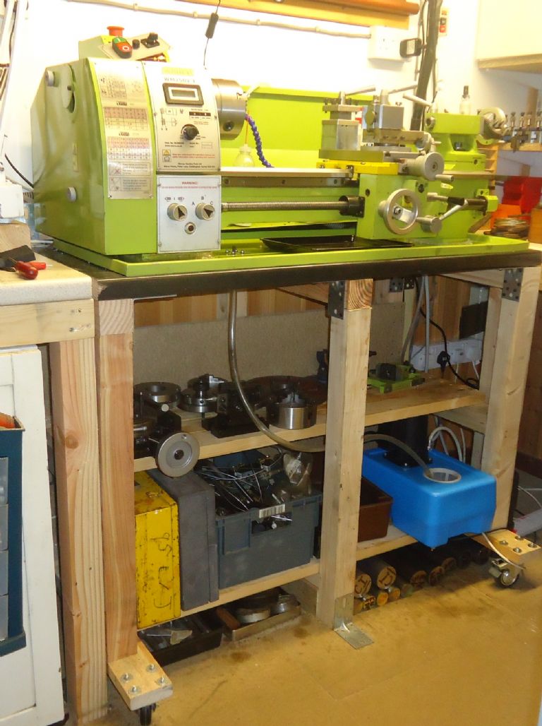
                                    As I said, moving this lot would hurt like 'ell:

                                    wm250 vf mounted.jpg

                                    #183335
                                    JasonB
                                    Moderator
                                      @jasonb

                                      Rik was there no circuit diagram in the manual? there is for my 280.

                                      #183337
                                      Rik Shaw
                                      Participant
                                        @rikshaw

                                        Thanks Jason – of course there is a schematic in my manual. Sometimes the obvious is not so obvious. Age perhaps?

                                        Rik

                                        #183338
                                        GarryC
                                        Participant
                                          @garryc

                                          Rik

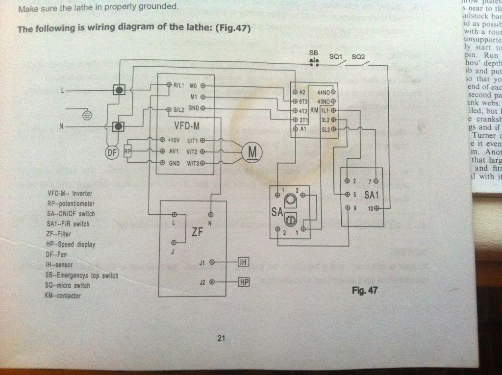
                                          In case this helps – its for the 'new' WM250V inverter drive model..

                                          wm250v wiring diagram..jpg

                                          Regards

                                          Allan.

                                          #183340
                                          Rik Shaw
                                          Participant
                                            @rikshaw

                                            Thanks Allan – I'll file that under future/maybe!

                                            Rik

                                            #183342
                                            Les Jones 1
                                            Participant
                                              @lesjones1

                                              Hi Rik,
                                              Does your lathe have a DC motor and speed controller or does it have a 3 phase motor and VFD as the schematic posted by Allan ? Can you post the poor picture of the schematic that you said you had of the schematic on the back of your lathe ? It may be good enough to see if it is the same as the one Allan posted.

                                              Les.

                                              #183350
                                              Rik Shaw
                                              Participant
                                                @rikshaw

                                                Hello Les – Mine is the old type DC motor and variable speed controller. Because my pic of the circuit diagram was so indistinct I have wiped it some time ago but I can tell you that it was different from Allans diagram. From now on I feel I am at the mercy of WARCO.

                                                GHMe

                                                Rik

                                                #189224
                                                Rik Shaw
                                                Participant
                                                  @rikshaw

                                                  Having in the last few weeks taken delivery of my repaired lathe from WARCO who had fitted a replacement speed control board I was looking forward this afternoon to running it up and doing a little work.

                                                  All went well for about twenty minutes albeit with the start button making its usual stuttering and false starts. No worries though as long as the thing worked – and then – I pressed the start button and the breaker tripped on the consumer unit in the workshop. Oh no, not again pleeease!

                                                  Tried starting again six times and each try the breaker tripped. By now I was beginning to feel slightly sick that my very expensive repair was for nothing.

                                                  Next thing I tried was to plug lathe into the house circuit and tried again. Press start button, chuck revolves briefly then lathe dies. What the four and a half is going on I thought.

                                                  Decided to check front panel fuse, it had blown. Replaced it and tried again. Same thing, another blown fuse and once again for luck, another blown fuse.

                                                  Replaced fuse, disconnected lathe from house circuit and plugged it back into workshop circuit. Pressed start button and the breaker tripped. Checked front fuse – it was still OK. Repeated several times with same result.

                                                  Apart from calling WARCO on Monday I am once again up a gum tree with a duff lathe again.

                                                  With the WM250 V-F out of its twelve month warranty but still under two years old from new I am reluctant to spend yet another £277 (or maybe more) on another repair which may or may not work.

                                                  Anyone want to buy a s/crap lathe?

                                                  Rik

                                                  #189233
                                                  Richard Marks
                                                  Participant
                                                    @richardmarks80868

                                                    Check the motor brushes for sticking in the holders and clean out any carbon dust around the brushes as this will cause tracking and will blow the trip, suggest checking and cleaning brushes annually, known fault from personal experience especially if you have an old current operated trip like mine.

                                                    #189322
                                                    Rik Shaw
                                                    Participant
                                                      @rikshaw

                                                      Thanks for that Richard, I'll check the brushes this afternoon. My consumer unit was only installed four years ago so I guess that should not count as old.

                                                      Rik

                                                    Viewing 25 posts - 26 through 50 (of 140 total)
                                                    • Please log in to reply to this topic. Registering is free and easy using the links on the menu at the top of this page.

                                                    Advert

                                                    Latest Replies

                                                    Viewing 25 topics - 1 through 25 (of 25 total)
                                                    Viewing 25 topics - 1 through 25 (of 25 total)

                                                    View full reply list.

                                                    Advert

                                                    Newsletter Sign-up