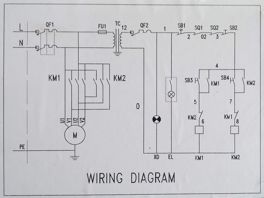
Warco VMC mill wiring diagram

Advert

Warco VMC mill wiring diagram

Home Forums Beginners questions Warco VMC mill wiring diagram

Viewing 11 posts - 1 through 11 (of 11 total)
  • Author
    Posts
  • #521379
    Duncan Harwell
    Participant
      @duncanharwell16936

      Hi all, I am new to the forum and enjoying the wealth of information.

      i am looking for some help with the wiring on my Warco VMC mill. I converted the mill to run VFD many years ago, and I did take a picture of the original wiring, however, you guessed it, no longer have the picture!

      As the machine is going to be sold I am converting back to original 240v and will use VFD on my new mill.

      The bulk of the wires have gone back without a problem as they are well numbered. The problem is the safety switches for the lid and chip guard. For the life of me I can’t work out the correct connections.

      If anyone can help with a wiring diagram or a photo I would appreciate it very much.

      Thanks

      Advert
      #10646
      Duncan Harwell
      Participant
        @duncanharwell16936
        #521465
        John Rudd
        Participant
          @johnrudd16576

          Duncan,

          The safety interlocks need to be wired in series, the series chain then connects in series with the Live feed to the NVR switch.

          I dont have a schematic but if you have most of the wiring back as was, it shouldnt be too difficult to figure out…

          The NVR switch needs a Live and Neutral going in ( with the series chained interlocks in the Live feed) then there should be a Live and Neutral coming out, feeding the Run winding of the motor, a Live and Neutral pair feeding the FWD-REV switch, which in turn has the Start winding connected to it. You may also have a Live Neutral feed going to a transformer for a lovo lamp.

          Let us know how you get on.

          In the meantime, I'll try and sketch something out…

          #521474
          John Rudd
          Participant
            @johnrudd16576

            I spotted an Ooops…

            I should have said the series chained interlocks are in series with the feed to the coil of the nvr switch…

            Cant add my sketch as its a pdf… angry Looks like I'll have try something else..

            #521475
            John Haine
            Participant
              @johnhaine32865

              Use snipping tool to take a copy of the pdf, then save as a jpg…

              #521476
              John Rudd
              Participant
                @johnrudd16576

                Wiring

                #521489
                Duncan Harwell
                Participant
                  @duncanharwell16936

                  John

                  Thank you so much for taking the time to reply, much appreciated. Would you mind if I sent you a picture of the set up on PM?

                  This, I’m sure is a easy fix all wiring is in place. The last wire I need to connect (007) comes from the NV switch pendant. It is Only connected to one side of the e-stop switch and then enters the main wiring compartment. All other wires in the pendant are connected as should be and are also connected in the FWD/rev sw. I think wire 007 makes the circuit incorporating the lid cut off switch? Just don’t know correct location in the switch to connect.

                  The issue is my lack of knowledge of electrics!
                  Many thanks

                  #521497
                  John Rudd
                  Participant
                    @johnrudd16576

                    Duncan,

                    not sure if pm caters for pictures,

                    I'll pm you my email address..

                    #521544
                    Glyn Davies
                    Participant
                      @glyndavies49417

                      This is the wiring diagram for my 2018 VMC:

                      wiring diagram.jpg

                      #521546
                      John Rudd
                      Participant
                        @johnrudd16576

                        Glyn,

                        That is just what is needed, many thanks…


                        Duncan, if you can identify SQ1&2, we can go from there…I suspect they are belt cover and chip guard interlocks.

                        Do you have a dvm at all?

                        Edited By John Rudd on 21/01/2021 16:31:50

                        #521549
                        Duncan Harwell
                        Participant
                          @duncanharwell16936

                          John and Glyn

                          Thank you so much for your help and advice. Now fixed!

                          Richard from Warco managed to find an older part exchange mill with the same wiring as my mill. He kindly took some pictures and the culprit wire 007 had to be connected with cut out switch to 003!!

                          They seem to have changed the wiring on the newer models like yours Glyn.

                          All the very best and thanks agin.

                        Viewing 11 posts - 1 through 11 (of 11 total)
                        • Please log in to reply to this topic. Registering is free and easy using the links on the menu at the top of this page.

                        Advert

                        Latest Replies

                        Home Forums Beginners questions Topics

                        Viewing 25 topics - 1 through 25 (of 25 total)
                        Viewing 25 topics - 1 through 25 (of 25 total)

                        View full reply list.

                        Advert

                        Newsletter Sign-up